Installation, operation & maintenance – AERCO Modulex General Manual User Manual
Page 22
INSTALLATION, OPERATION & MAINTENANCE
2-6
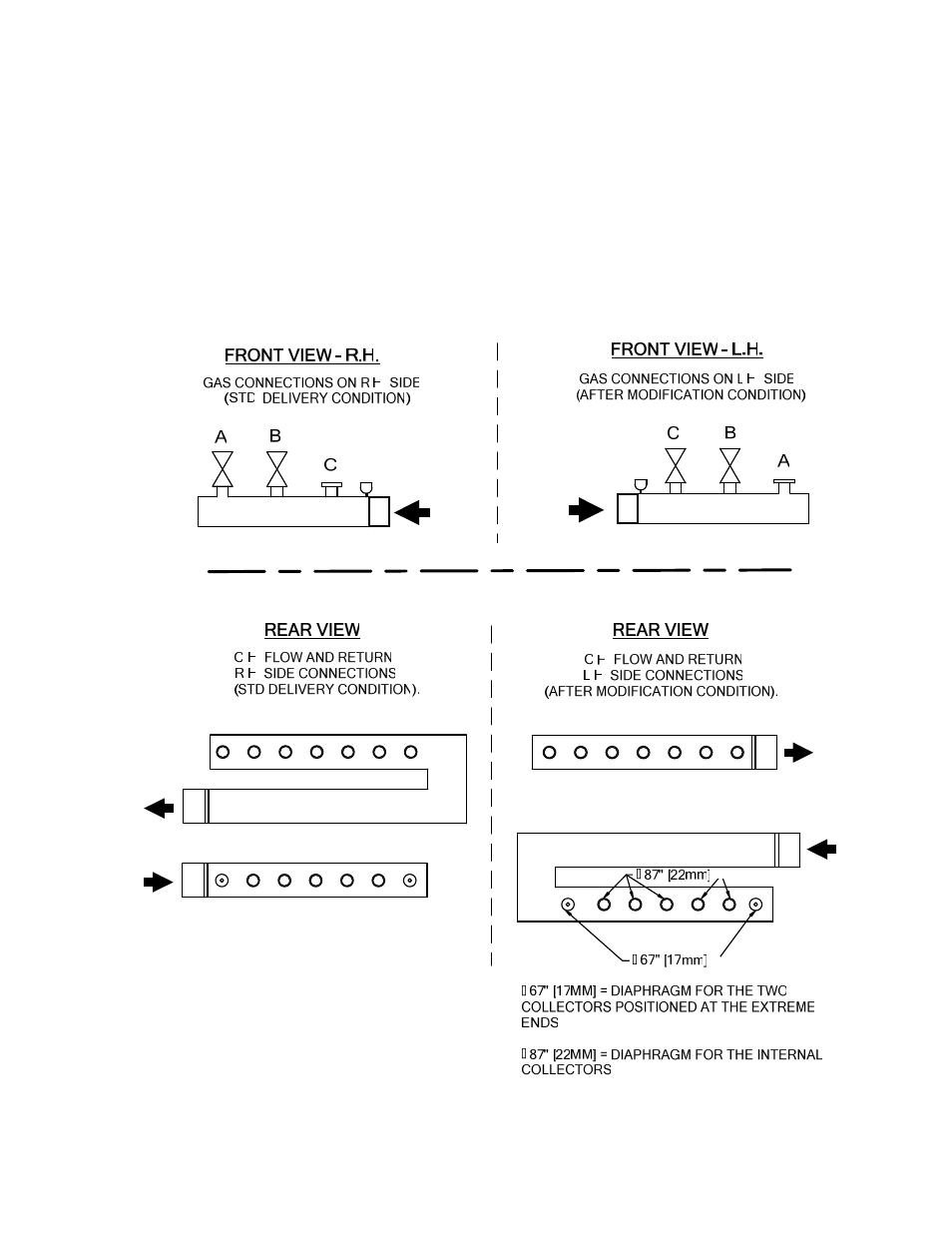
3. Disassemble the flow (supply) and return manifolds (Figure 2-5), leaving the rubber gaskets in place
on the upper holes of the aluminum sections and the diaphragms in place on the lower holes. The
diaphragms on the end sections have a hole diameter of .669 in. (17 mm), while the gaskets on the
upper holes have a hole diameter of .866 in. (22 mm).
4. Reassemble the manifolds with the threaded connection on the opposite side as shown in Figure
2-5. Change the position of the drain cock and the automatic air vent (Figure 2-6).
5. Reposition the temperature sensor white and red leads onto the new flow (supply) manifold and the
temperature sensor white and green leads onto the new return manifold.
Figure 2-5
R.H. and L.H. Manifold Connection
- AERClean (12 pages)
- ProtoNode Gateway Rev 1 (with internal LEDs) (64 pages)
- ProtoNode Gateway Rev 3 (with external LEDs) (126 pages)
- Control System (ACS) (144 pages)
- Belimo F6...HD/HDU Series Valve (44 pages)
- Belimo AF120-S US Actuator (9 pages)
- Belimo AMX24-MFT Actuator (9 pages)
- Belimo GKX24-MFT Actuator (9 pages)
- Belimo Motorized Valves Installation (20 pages)
- BMS II BOILER (108 pages)
- BMS II BOILER MODBUS Communication (100 pages)
- BMS 168 (86 pages)
- Boiler Valve Controller (BVC) PRIOR to Serial-12-840-1 (35 pages)
- Boiler Valve Controller (BVC) (38 pages)
- Buffer Tanks (14 pages)
- Combination Control Panel (CCP) (4 pages)
- XPC GATEWAY Communications (193 pages)
- Domestic Water Storage Tank (19 pages)
- Steam Traps (6 pages)
- X100 – Inhibitor (4 pages)
- AM Series Boiler User Manual (156 pages)
- AM Series Boiler Cascade Sequencer Controller (26 pages)
- AM Series Boiler Modbus Interface Manual (18 pages)
- BMK 1.5 LN October 2012 (166 pages)
- BMK 1.5 LN July 2011 (152 pages)
- BMK 1.5 LN June 2010 (123 pages)
- BMK 1.5 LN May 2009 (111 pages)
- BMK 1.5 LN Dual Fuel Feb 2013 (162 pages)
- BMK 1.5 LN Dual Fuel June 2010 (139 pages)
- BMK 1.5 LN Dual Fuel Jan 2009 (126 pages)
- BMK 1500-2000 (188 pages)
- BMK 1500DF (196 pages)
- C-More Control Panel (162 pages)
- BMK 2.0 LN October 2012 (172 pages)
- BMK 2.0 LN Natural Gas (SN G-11-1861 and above) (170 pages)
- BMK 2.0 LN Nat. Gas June 2010 (125 pages)
- BMK 2.0 LN Natural Gas 2008 (111 pages)
- BMK 2.0 LN Nat. Gas for Mass. only (113 pages)
- BMK 2.0 LN Dual Fuel Serial G-11-2402 and UP (160 pages)
- BMK 2.0 LN Dual Fuel Nov 2010 (139 pages)
- BMK 2.0 LN Nat. Gas (112 pages)
- BMK 2.0 LN for Mass. only (114 pages)
- BMK 3.0 LN Dual-Fuel Series Gas Fired Low NOx Boiler System (136 pages)
- BMK 3.0 LN Natural Gas July 2011 (129 pages)
- BMK 3.0 LN Nat. Gas Jan 2011 (129 pages)