Installation, operation & maintenance – AERCO Modulex General Manual User Manual
Page 18
INSTALLATION, OPERATION & MAINTENANCE
2-2
Packed inside the boiler packing you will find:
• Painted steel panels:
• The front one connected to the back panel by a shrink wrap film
• The right hand side panel connected to the left hand panel by shrink wrap
On the front of the boiler:
• Flue collector, with exhaust connector screwed to the pallet: 6 inch for models 303 to 606 and 8
inch for models 757 to 1060. Use these items only when the specified flue pipe size is increased
to 6” (for models 303 to 606) and 8” (for models 757 to 1060). Otherwise, use the exhaust
connector “shipped in the separate carton” described below (4” for models 303 to 606, 6” for
models 757 to 1060).
• A plastic bag containing 3 gaskets (1 rectangular for condensate tray and flue collector, 1 square
for exhaust connector.
• Three (3) surface-mount strap-on sensors.
• Screws necessary for accessory installation.
• Piping for 1 ½” condensate drain, including one tee and two 90 degree elbows.
On the back of the boiler:
• Plastic condensate drainpipe, 38.5 inches (1meter) long, placed under the casing rear panel.
• Outside air sensor with 49 feet, 2.5 inches (15 m) cable.
• Manual Gas Shutoff Valve.
Shipped in a separate carton are the following:
• Accessory kit that includes a CSD-1 installation kit, P/N 29031 for Models 303 through 606 and
P/N 29032 for Models 754 through 1060. See the packing list shipped in this manual package for
a complete listing of accessories and paragraph 4.4 for more information about the CSD 1- kits.
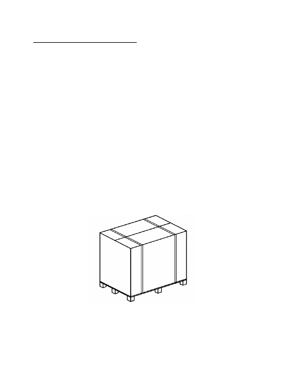
Figure 2-1.
Packaged Modulex Boiler