Figure 7.2, Grounding terminal location, Figure 7.3 – AERCO KC1000 Boiler equipped with C-More 2002 User Manual
Page 66: Burner disassembly diagram, Figure 7.4, Exhaust sensor connector location, Figure 7.5, Blower proof switch wire locations, Maintenance
MAINTENANCE
7-3
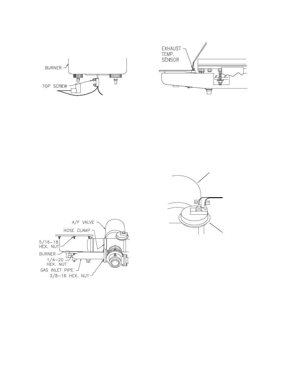
6. Remove the grounding terminal from the
burner by loosening the upper screw and
sliding the connector from the grounding rod.
(See Fig. 7.2)
Figure 7.2
Grounding Terminal Location
7. Using a 7/16” socket or open end wrench
remove the four 1/4”-20 nuts on the gas inlet
pipe flange at the burner (See Fig. 7.3).
8. Using two 9/16” wrenches remove the 3/8"-
16 hex nuts and bolts on the gas inlet pipe
flange at the air/fuel valve (See Fig. 7.3).
9. Loosen the hose clamp nearest the air/fuel
valve outlet on the air/fuel valve to burner
adapter (See Fig. 7.3).
10. Using a 1/2” socket wrench remove six
5/16-18 hex nuts supporting the burner (See
Fig. 7.3).
Figure 7.3
Burner Disassembly Diagram
11. Lower the burner while sliding the air hose
off the air/fuel valve. Remove the burner
through the rear of the unit.
12. Disconnect the exhaust temperature sensor
by unscrewing it from the exhaust manifold
(See Fig. 7.4).
Figure 7.4
Exhaust Sensor Connector Location
13. Disconnect the air/fuel valve wire harness,
the 12 pin connector, from the control panel.
14. Disconnect wires #24 and #17 from the
blower proof switch (See Fig. 7.5).
TO FRAME
HARNESS
BLOWER PROOF
SWITCH
AIR/FUEL VALVE
Figure 7.5
Blower Proof Switch Wire Locations
15. Loosen the hose clamp on the air/fuel valve
inlet and slide the clamp back towards the
blower (See Fig. 7.6).