1 constant setpoint mode, Figure 2.11, I/o box terminal strip – AERCO KC1000 Boiler equipped with C-More 2002 User Manual
Page 17: Boiler management system (bms) mode, 4 remote setpoint and direct drive modes, Installation, 2 indoor/outdoor reset mode, Danger
INSTALLATION
2-7
2.6.1 CONSTANT SETPOINT MODE
The Constant Setpoint Mode is used when it is
desired to have a fixed setpoint that does not
deviate. No wiring connections other than
electrical supply connections are required for
this mode. However, if desired, fault monitoring
or enable/disable interlock wiring can be utilized
(see paragraphs 2.7.9 and 2.7.10).
2.6.2 INDOOR/OUTDOOR RESET MODE
This mode of operation increases supply water
temperature as outdoor temperatures decrease.
An outside air temperature sensor (AERCO PN
122790) is required. The sensor MUST BE
wired to the I/O Box wiring terminals (see Fig.
2.11). For more information concerning the
outside air sensor installation, refer to paragraph
2.7.1. For programming and setup instructions
concerning the indoor/outdoor-reset mode of
operation, refer to Section 5, paragraph 5.1.
.
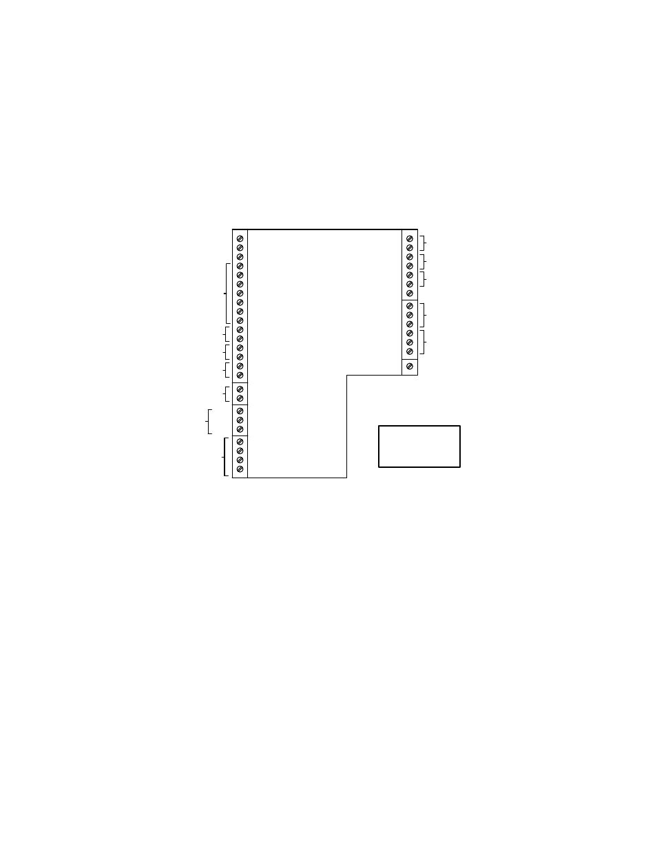
mA OUT
RS-485
COMM.
+
-
+
-
ANALOG IN
SENSOR COMMON
OUTDOOR SENSOR IN
REMOTE INTL'K IN
B.M.S. (PWM) IN
SHIELD
+
-
+
-
AUX SENSOR IN
NOT USED
EXHAUST SWITCH IN
DELAYED INTL'K IN
FAULT RELAY
120 VAC, 5A, RES
AUX RELAY
120 VAC, 5A, RES
G
RELAY CONTACTS:
120 VAC, 30 VDC
5 AMPS RESISTIVE
DANGER
120 VAC USED
IN THIS BOX
NOT USED
NOT USED
NC
COM
NO
NC
COM
NO
NOT USED
Figure 2.11
I/O Box Terminal Strip
2.6.3 BOILER MANAGEMENT SYSTEM
(BMS) MODE
NOTE
BMS Model 168 can utilize either pulse
width modulation (PWM) or RS485
Modbus signaling to the Boiler. BMS II
Model 5R5-384 can utilize only RS485
signaling to the Boiler.
When using an AERCO Boiler Management
System (BMS), the field wiring is connected
between the BMS Panel and each Boiler’s I/O
Box terminal strip (Figure 2-11). Twisted
shielded pair wire from 18 to 22 AWG must be
utilized for the connections. The BMS Mode can
utilize either pulse width modulation (PWM)
signaling, or RS485 Modbus signaling. For PWM
signaling, connections are made from the
AERCO Boiler Management System to the
B.M.S. (PWM) IN terminals on the I/O Box
terminal strip. For RS485 Modbus signaling,
connections are made from the BMS to the
RS485 COMM terminals on the I/O Box terminal
strip. Polarity must be maintained and the shield
must be connected only at the AERCO BMS.
The boiler end of the shield must be left floating.
For additional instructions, refer to Chapter 5,
paragraph 5.6 in this manual. Also, refer to GF-
108M (BMS Model 168) and GF-124 (BMS II
Model 5R5-384), BMS -Operations Guides.
2.6.4 REMOTE SETPOINT and DIRECT
DRIVE MODES
The KC1000 Boiler can accept several types of
signal formats from an Energy Management
System or other source to control either the
setpoint (Remote Setpoint Mode) or firing rate