Figure 2.8, Ac power box location, Ac power wiring diagram – AERCO KC1000 Boiler equipped with C-More 2002 User Manual
Page 16: Figure 2.10, Input/output (i/o) box location, Installation
INSTALLATION
2-6
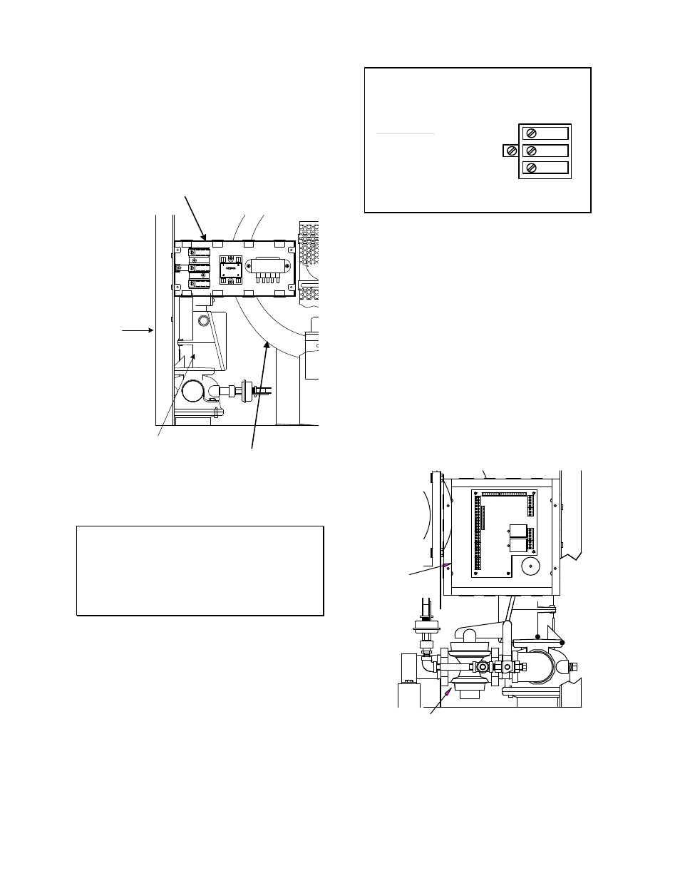
connection to the unit are made at the Power
Box.This box is located on the front right side of
the unit as shown in Figure 2.8. Conduit should
be run from the knockouts in the side of the box
in such a manner that it does not interfere with
the removal of any sheet metal covers. A flexible
electrical connection may be utilized to allow the
covers to be easily removed.
POWER BOX
BLOWER
SSOV
ACTUATOR
FRAME
Figure 2.8
AC Power Box Location
NOTE:
All electrical conduit and hardware should
be installed so that it does not interfere with
the removal of any cover, inhibit service or
maintenance, or prevent access between
the unit and walls or another unit.
2.5.1 ELECTRICAL REQUIREMENTS
Electrical requirements for each unit are 120
VAC, 1 Phase, 60 Hz, 20 Amps from a
dedicated electrical circuit. No other devices
should be on the same electrical circuit as a
KC1000 unit. A means for disconnecting AC
power from the unit (such as a service switch)
must be installed near the unit for normal opera-
tion and maintenance. All electrical connections
should be made in accordance with the National
Electrical Code and/or with any applicable local
codes.
The AC power wiring diagram is shown in Figure
2.9.
USE COPPER CONDUCTORS ONLY FOR FIELD WIRING
60 HZ
DISCONNECT POWER BEFORE SERVICING
DANGER: HIGH VOLTAGE
20 AMP
120 VAC,
NEUTRAL
GROUND
LINE
POWER BOX
AERCO INTERNATIONAL INC.
INPUT POWER
Figure 2.9
AC Power Wiring Diagram
2.6 MODE OF OPERATION and FIELD
CONTROL WIRING
The KC Boiler is available in several different
modes of operation. While each unit is factory
configured and wired for the mode specified on
the equipment order, some field wiring may be
required to complete the installation. This wiring
is typically routed to the Input/Output (I/O) Box
located on the left side of the unit beneath the
removable side panel (see Fig. 2.10). Field
wiring for each particular mode of operation is
described in the following paragraphs. For
additional information concerning modes of
operations, refer to Section 5.
I/O
BOX
GAS SHUT-OFF VALVE
BLOWER
Figure 2.10
Input/Output (I/O) Box Location