Safety device testing – AERCO BMK 1.5 LN Dual Fuel June 2010 User Manual
Page 54
SAFETY DEVICE TESTING
9. Press the CLEAR button. The unit should
restart.
10. Next, check the Blocked Inlet Switch by first
noting the current position of the Iris Air
Damper and then closing the Damper to
position 8.
11. The unit should shut down and again display
AIRFLOW FAULT DURING RUN
.
12. Return the Iris Air Damper to its previous
setting.
13. Press the CLEAR button. The unit should
restart.
6.11 SSOV PROOF OF CLOSURE
SWITCH
This test can be performed when the unit is set
up to run on either natural gas or propane fuel.
Both the Natural Gas and Propane SSOVs
contain proof of closure switches which are
wired in series.
1. Set the unit’s ON/OFF switch to the OFF
position.
2. Place the unit in Manual Mode and set the
valve position between 25% and 30%
3. Refer to Figure 6-1 and locate the Natural
Gas SSOV.
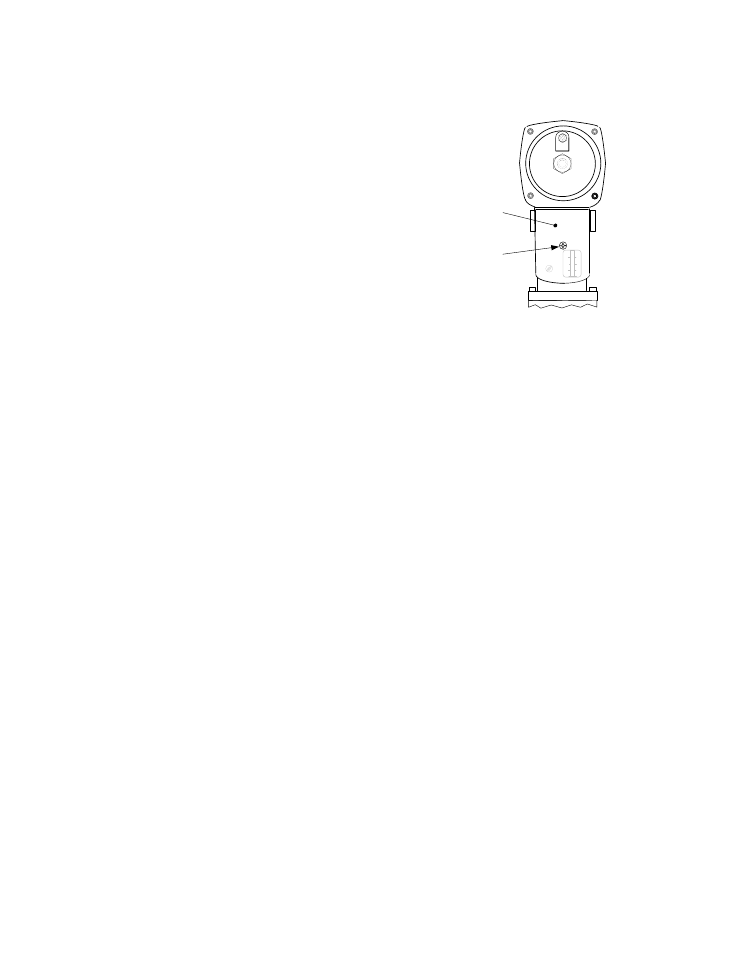
4. Remove the cover from the SSOV by
loosening the screw shown in Figure 6-4. Lift
off the cover to access the terminal wiring
connections.
5. Disconnect wire #148 from the SSOV to
“open” the proof of closure switch circuit.
6. The unit should fault and display SSOV
SWITCH OPEN.
7. Replace wire #148 and press the CLEAR
button.
8. Set
the
ON/OFF
switch to ON to restart the
unit.
9. Remove the wire again when the unit
reaches the purge cycle and PURGING is
displayed.
10. The unit should shut down and display
SSOV FAULT DURING PURGE.
11. Replace wire #148 on the SSOV and press
the CLEAR button. The unit should restart.
ACTUATOR
COVER
SCREW
SSOV
ACTUATOR
COVER
Figure 6-4
SSOV Actuator Cover Location
6.12 PURGE SWITCH OPEN DURING
PURGE
The Purge Switch (and Ignition Switch) is
located on the Air/Fuel Valve. To check the
switch, proceed as follows:
1. Set the unit’s ON/OFF switch to the OFF
position. Place the unit in manual mode and
set the valve position between 25% and
30%.
2. Remove the Air/Fuel Valve cover by rotating
the cover counterclockwise to unlock it and
then remove the cover (see Figure 6-5).
3. Remove one of the two wires (#171 or #172)
from the Purge Switch (Figure 6-6).
4. Initiate a unit start sequence.
5. The unit should begin it’s start sequence,
then shut down and display PRG SWITCH
OPEN DURING PURGE.
6. Replace the wire on the Purge Switch and
depress the CLEAR button. The unit should
restart.
6-6