Installation – AERCO BMK 1.5 LN Dual Fuel June 2010 User Manual
Page 14
INSTALLATION
2-4
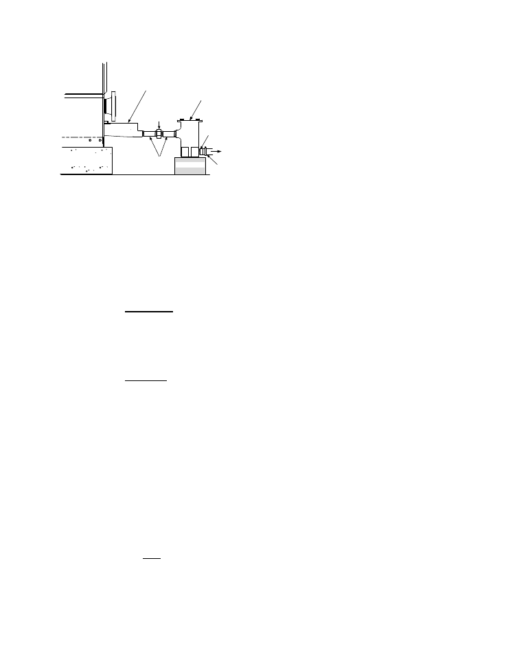
PARTIAL RIGHT SIDE VIEW
3/4" NPT
NIPPLE
1" I.D.
HOSE &
CLAMP
EXHAUST
MANIFOLD
CONDENSATE
TRAP
TO
FLOOR
DRAIN
3/4" NPT
NIPPLES
UNION
HOUSEKEEPING
PAD
SUPPORT
Figure 2-5
Condensate Trap Installation
2.7 GAS SUPPLY PIPING
The AERCO Benchmark 1.5 Gas Components
and Supply Design Guide, GF-4030 must be
consulted prior to designing or installing any gas
supply piping.
WARNING
NEVER USE MATCHES, CANDLES,
FLAMES OR OTHER SOURCES OF
IGNITION TO CHECK FOR GAS
LEAKS
.
CAUTION
Many soaps used for gas pipe leak
testing are corrosive to metals. There-
fore, piping must be rinsed thoroughly
with clean water after leak checks
have been completed.
NOTE
All gas piping must be arranged so that it
does not interfere with removal of any
covers, inhibit service/maintenance, or
restrict access between the unit and
walls, or another unit.
Benchmark 1.5 Dual-Fuel units contain two
1-1/2 inch gas inlet connections on the rear of
the unit as shown in Figure 2-3. If one of the
fuel sources is not being piped due to its
unavailability, the inlet must be capped.
Prior to installation, all pipes should be de-
burred and internally cleared of any scale, metal
chips or other foreign particles. Do Not install
any flexible connectors or unapproved gas
fittings. Piping must be supported from the floor,
ceiling or walls only and must not be supported
by the unit.
A suitable piping compound, approved for use
with natural gas, should be used. Any excess
must be wiped off to prevent clogging of
components.
To avoid unit damage when pressure testing gas
piping, isolate the unit from the gas supply
piping. At no time should the gas pressure
applied to the unit exceed 2 psi. Leak test all
external piping thoroughly using a soap and
water solution or suitable equivalent. The gas
piping used must meet all applicable codes.
2.7.1 Gas Supply Specifications.
The gas supply input specifications to the unit
for Natural Gas and Propane are as follows:
• Natural Gas - The maximum static pressure
to the unit must not exceed 2 psi. The gas
supply pressure to the unit must be of
sufficient capacity to provide 1500 cfh while
maintaining the gas pressure at 4 inches
W.C. for FM ,or 4.2 inches W.C. for IRI gas
trains.
• Propane - The maximum static pressure to
the unit must not exceed 2 psi. The gas
supply pressure to the unit must be of
sufficient capacity to provide 600 cfh while
maintaining the gas pressure at 4.0 inches
W.C. for FM, or 4.2 inches W.C. for IRI gas
trains.
The maximum static pressure to the unit must
not exceed 2 psi. The minimum operating gas
pressure for natural gas is 4 inches W.C. for
both FM and IRI gas trains when the unit is firing
at maximum input. The gas supply pressure to
the unit must be of sufficient capacity to provide
1500 cfh while maintaining the gas pressure at 4
inches W.C. for FM or IRI gas trains.
2.7.2 Manual Gas Shutoff Valve
A manual shut-off valve must be installed in the
gas supply line upstream of the Boiler as shown
in Figure 2-6. Maximum allowable gas pressure
to the Boiler is 2 psi