KEYENCE N-48/42 User Manual
Page 8
8
The following I/O connections are common for
both the N-42 and N-48.
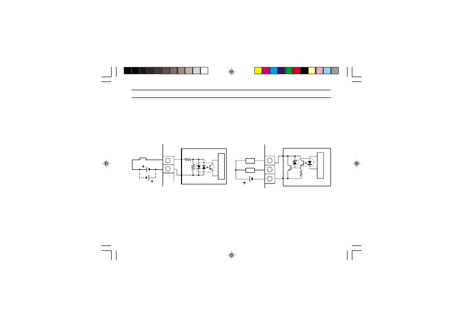
■
Connecting trigger input
The trigger input allows the BL series to start
reading bar codes. The trigger input turns ON
when 15 to 26 VDC input is activated.
INPUT/OUTPUT CONNECTIONS
■
Connecting OK/NG output
The BL series uses OK/NG output to compare
the read data with the preset data, or to judge
whether a bar code can be correctly read.
*
Rated load: 30 VDC (100 mA)
*
The above circuit diagram shows OK output
only. NG output is provided in the same way.
15 to 26 VDC
TIM
COM
Contact or
solid-state
Inter
nal circuit
OK
NG
COM
Load
Load
Inter
nal circuit
See also other documents in the category KEYENCE Sensors:
- LR-TB2000 Series (12 pages)
- LR-TB5000 Series (12 pages)
- LR-ZB250AN/AP (4 pages)
- LR-ZB250AN/P (3 pages)
- LR-ZBxN/P Series (3 pages)
- LR-ZBxxB (3 pages)
- OP-85135 (1 page)
- PZ-G Series (2 pages)
- PZ-V/M (2 pages)
- PS-N10 Series (12 pages)
- PX-10 (10 pages)
- CZ-V21A(P) (10 pages)
- CZ-K1(P) (8 pages)
- CZ-V1 (8 pages)
- FS-N10 Series (116 pages)
- FS-N10 Series (6 pages)
- FS-N15CN (1 page)
- FU-93(Z) (2 pages)
- FU-V Series (2 pages)
- FS-V30 (6 pages)
- FU-A40 (1 page)
- NU/FS-N Series (16 pages)
- FS-V33(P) (8 pages)
- FS-V21 (4 pages)
- FS-V22 (4 pages)
- FS-V11(P) (4 pages)
- FS-V1(P) (4 pages)
- LV-N10 Series (12 pages)
- LV-N10 Series (112 pages)
- LV-S62 (1 page)
- OP-84350 (1 page)
- LV-SA (10 pages)
- LV-SB (12 pages)
- OP-87305 (1 page)
- LV Series (10 pages)
- LV-B102 (1 page)
- EV-108M(U) (1 page)
- EZ Series (1 page)
- EM Series (1 page)
- ES-M1(P) (3 pages)
- EX-V Series (120 pages)
- EX-500(W) Series (16 pages)
- GV Series (10 pages)
- IA Series (8 pages)
- LB-1000(W) (24 pages)