Part names and functions, Initial settings of the n-l1, System configuration figure – KEYENCE N-L1 User Manual
Page 2: Connection and wiring methods, Connecting the code reader, Connecting the power supply, Layout and wiring of the i/o terminal block, Kv -b16xc
2
E N-L1-IM
•
Method of using the RESET/RUN switch
■ Initial settings of the N-L1
When the N-L1 is turned on with the RESET switch set to ON, the initial
settings of the Ethernet is as follows:
■ Connecting the code reader
Connect the code reader to the head port of the N-L1.
Pin layout of the head port
■ Connecting the power supply
Connect the 24 VDC power supply to the power terminal of the N-L1.
The dimensions of crimp contacts used for wiring should be as follows:
■ Layout and Wiring of the I/O Terminal Block
•
Layout of the I/O terminal block
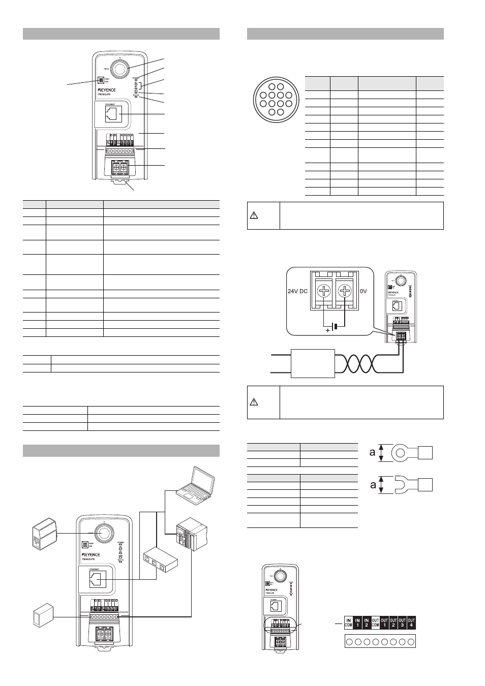
Part Names and Functions
Number
Name
Function
1
Head port
Used to connect the head.
2
Power LED
Lights when the power is ON.
3
Communication status
LED
Monitors the status of communication with the
head.
4
LINK LED
Lights when the communication with an
Ethernet unit is established.
5
100/10 LED
Lights when there is 100 Mbps
communication. Goes off when there is 10
Mbps communication.
6
Ethernet connection
port
Used to connect to an Ethernet unit.
7
I/O status LED
Monitors the ON/OFF status of I/O terminals.
8
I/O terminal
Used to connect I/O signal lines of control
units.
9
Power terminal
Terminal for 24V DC power supply input.
10
DIN rail mounting tab
A tab for mounting the DIN rail.
11
RESET/RUN switch
A switch for switching the setting/run mode
RESET
For setting the N-L1 such as IP addresses, set it to the RESET side.
RUN
To switch to the run mode, set it to the RUN side.
IP address
192.168.0.1
Subnet mask
255.255.255.0
Default gateway
0.0.0.0
System Configuration Figure
10. DIN rail mounting tab
11. RESET/RUN switch
1. Head port
2. Power LED
3. Communication
status LED
4. LINK LED
5. 100/10 LED
6. Ethernet
connection port
7. I/O status LED
8. I/O terminals
9. Power terminal
KV
-B16XC
Head port
Input
terminal
OUT1 to 4
IN1
Head
BL Series
SR Series
Personal
computer
PLC
Timing sensor
Ethernet port
HUB
Connection and Wiring Methods
Pin
number
Name
Signal name
Signal
direction
1
OUT1
OUT1 input
Input
2
OUT2
OUT2 input
Input
3
RXD
RS-232C Receive
Input
4
RTS
RS-232C Receivable
Output
5
OUT4
OUT4 input
Input
6
IN2
IN2 output
Output
7
TXD
RS-232C Transmit
Output
8
CTS
RS-232C
Transmittable
Input
9
OUT3
OUT3 input
Input
10
IN1
IN1 output
Output
11
+5V
+5V power supply
Output
12
GND(SG)
Common GND
-
CAUTION
Install and remove connection cables with the power
disconnected.
CAUTION
• Using a power supply other than 24 VDC may cause
product failure.
• The N-L1 does not support PoE (Power over Ethernet).
Be sure to supply 24 VDC power to the power terminal.
Terminal
Dimensions
Round Terminal
a: 6 mm Max.
Y terminal
a: 6 mm Max.
Item
Description
Wire size
AWG14-22
Tightening torque
0.49 N·m (4.34 lbf·in)
Wire material
Copper
Wire type
Stranded wire
Electric wire
temperature rating
+60
°C max.
3
7
4
8
5
1
2
9
11
12
6
10
Round 12-pin jack
Power supply
24V+10%
-20%
Twist pair cable
I/O terminal
block