KEYENCE OP-87362 User Manual
Ethernet assembly plug, Assembly instruction manual
Ethernet assembly plug
OP-87362
Assembly instruction manual
Use OP-87362 when making the Ethernet cable by yourself to connect to the
SR-650 Series.
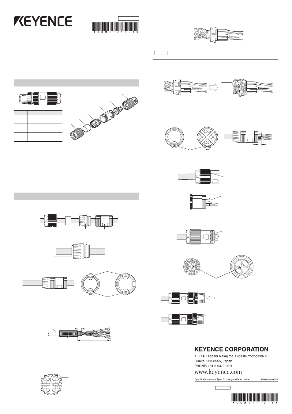
Parts configuration
Prepare the following
• Ethernet cable
: Use the STP cable of CAT5e or more.
(Compliant cable: AWG26, outer
shape of the cable=
I4 to 8 mm)
• Adhesive to prevent screw loosening:This is used to fix the plug head
and sleeve. Prepare this separately.
* Recommended adhesive:
LOCTITE 262, 263 (HENKEL
Corporation)
Assembly procedure
1
Insert the nut, grommet, collar and sleeve into the Ethernet cable
beforehand.
2
Push the grommet into the collar.
3
Insert to the sleeve.
4
Remove the sheath (outer covering) of the Ethernet cable.
Fold the braided shield back and cover the sheath (outer covering).
Remove the aluminum foil shield from the pair core with 8 to 10 mm left.
5
Insert the core wire to the core holder.
Unwind each twisted wire and insert one by one. The wire colors should
match with the colors of the core holder.
The core wires have been twisted for each signal wire. When inserting the
core wires into the core holder, insert each twisted pair wire.
After all the core wires are inserted, push the core holder in until it hits the
aluminum foil shield.
6
Twist the shield wire along the core holder.
Hook the shield wire on the claws of the core holder when wrapping. Cut
off the surplus shield wire.
7
Insert the core holder to the sleeve.
Align the claws of the core holder with the protrusion positions of the
sleeve and insert to the end.
After pushing the core holder into the end, tighten the nut to the sleeve.
(Tightening torque: 1.0N•m)
8
Cut the core wire according to the core holder size.
9
Apply one or two drops of adhesive to the screw part of the sleeve.
Make sure that the adhesive does not touch the core wire or pins inside
the plug head.
10
Tighten the plug head to the sleeve.
Tighten while pushing in the plug head. (Tightening torque: 2.0N•m)
Tighten until the screw stand is hidden.
11
Leave it for about 30 minutes in ambient temperature until the
adhesive is fixed.
96M11710
(1)
(2)
(3)
(4)
(5)
(6)
Number
Part names
(1)
nut
(2)
grommet
(3)
collar
(4)
sleeve
(5)
core holder
(6)
plug head
RJ-45 side
SR-650 side
nut
grommet
collar
sleeve
Push securely into
the end.
Align the dent positions of the collar with the
protrusion positions of the sleeve to insert.
collar
sleeve
Sheath
Braided shield
50 to 70 mm
aluminum foil shield: 8 to 10 mm
Insert the twisted pair wires to the
same block.
Before inserting, check that the colors of core wires match with the colors of
the core holder. Also, make sure to insert the pair core wires to the same
block. Wrong wiring may cause communication failure.
NOTICE
Make sure that the braided shield wire covers up to the above dotted line.
Hook the braided shield wire on the claws when wrapping and cut off the surplus shield wire.
Align the four positions and push in.
2.8 to 3.0 mm
Tighten until the screw
stand is hidden.
Cut the core wire according
to the core holder size.
Make sure to apply the adhesive
to the screw part.
Align the cutout of the core holder with the protrusion position of the plug head.
Tighten while pushing in.
Tighten until the screw stand is hidden.
If tightening becomes difficult halfway, push with force.
Then, the screw will rotate smoothly.
Completely wipe away adhesive pushed out from the
inside of the screw stand.
Copyright (c) 2011 KEYENCE CORPORATION. All rights reserved.
11710E 1042-1 96M11710 Printed in Japan