Connecting the 24 vdc power source, Parallel i/o interface, Connector specifications – KEYENCE CV-5001 Series User Manual
Page 5: Parallel i/o assignment: when using cable op-51657
5
Connecting the 24 VDC Power Source
Supply 24 VDC to terminal number 7 and 8 of the IN connector.
• Use a slotted screwdriver to connect to the terminals.
• Use a torque of 0.25 Nm or less to tighten the screws.
• Use the electrical wires AWG14 to AWG22.
• Make sure to connect the frame ground terminal for the 24 VDC power
source to a type D ground.
• Do not supply power until installation is complete.
1
After stripping the insulating sheath by about 7 mm, insert
the lead wires into terminal No. 7 (24 VDC) and No. 8 (0 V),
and then insert the I/O terminal block into the I/O connector
as far as it can go.
2
Connect the ground wire to the ground port.
• Ground each device separately.
• Use a D type ground.
• Keep ground resistance under 100 Ω.
• Keep the ground wire as short as possible.
• If it is not possible to ground each device separately, ground them
together. However, make sure that the electrical cables are the same as
shown below.
• Solderless contact sizes are listed below. M4 screws should be used.
• Tighten the screws with a torque of 0.8 [Nm].
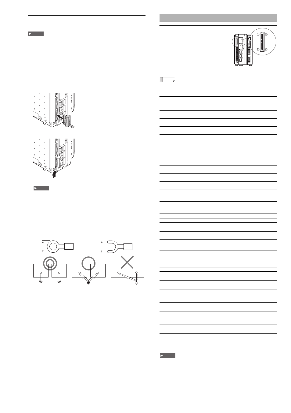
Connector Specifications
The following values show the parallel I/O
connector specifications for the system.
Connector
FX2B-40SA-1.27R (Hirose Electric)
Color flat cable
UL20028-FRX-CF-40 (Fujikura,
equivalent wire gauge AWG28)
In normal situations, use the specialized parallel connection cable (3 m)
OP-51657 (sold separately).
Parallel I/O Assignment: When Using Cable OP-51657
(Sold Separately)
• COMOUT2 for Pin 17 and Pin 40 are common.
• COMIN2 is a common terminal for input for the parallel I/O connector.
• COMOUT2 is a common terminal for output for the parallel I/O connector.
• Power source 0 V and COMIN1, COMIN2, COMOUT1, COMOUT2,
COMOUT_F+, and COMOUT_F- are all isolated.
Note
Connect the ground wire
Note
8.5 mm or
smaller
Circular connector
D-type ground* (third ground)
(ground resistance 100
Ω)
A = B
D-type ground* (third ground)
(ground resistance 100
Ω)
A > B
A < B
Device
Peripheral
Device
Peripheral
A
B
Device
Peripheral
A
B
8.5 mm or smaller
Y connector
Parallel I/O Interface
No.
Signal
Signal description
Signal
direction
Circuit
diagram
Cable
color
1
COMIN2
Connector input common
terminal
–
–
Brown
2
IN0
(Command parameter)
Command parameter
input bit 0 (LSB)
Input
B
Red
3
IN1
(Command parameter)
Command parameter
input bit 1
Input
B
Orange
4
IN2
(Command parameter)
Command parameter
input bit 2
Input
B
Yellow
5
IN3
(Command parameter)
Command parameter
input bit 3
Input
B
Green
6
IN4
(Command parameter)
Command parameter
input bit 4
Input
B
Blue
7
IN5
(Command parameter)
Command parameter
input bit 5
Input
B
Purple
8
IN6
(Command parameter)
Command parameter
input bit 6
Input
B
Gray
9
IN7
(Command parameter)
Command parameter
input bit 7 (MSB)
Input
B
White
10 IN8 (Command type)
Command input bit 0
(LSB)
Input
B
Black
11 IN9 (Command type)
Command input bit 1
Input
B
Brown
12 IN10 (Command type)
Command input bit 2
Input
B
Red
13 IN11 (Command type)
Command input bit 3
(MSB)
Input
B
Orange
14 CST
Command execution input
Input
B
Yellow
15 RESET Reset
Input
B
Green
16 PST
Output data cycle input
Input
B
Blue
17 COMOUT2
Output common terminal
–
–
Purple
18 ACK
Verification of successfully
executed command input
Output
D
Gray
19 NACK
Verification of
unsuccessfully executed
command input
Output
D
White
20 BUSY Busy
signal
Output
D
Black
21 CMD_READY
Command input
permission
Output
D
Brown
22 READY1
Trigger 1 input permission
Output
D
Red
23 READY2
Trigger 2 input permission
Output
D
Orange
24 OUT0
Data output bit 0 (LSB)
Output
D
Yellow
25 OUT1
Data output bit 1
Output
D
Green
26 OUT2
Data output bit 2
Output
D
Blue
27 OUT3
Data output bit 3
Output
D
Purple
28 OUT4
Data output bit 4
Output
D
Gray
29 OUT5
Data output bit 5
Output
D
White
30 OUT6
Data output bit 6
Output
D
Black
31 OUT7
Data output bit 7
Output
D
Brown
32 OUT8
Data output bit 8
Output
D
Red
33 OUT9
Data output bit 9
Output
D
Orange
34 OUT10
Data output bit 10
Output
D
Yellow
35 OUT11
Data output bit 11
Output
D
Green
36 OUT12
Data output bit 12
Output
D
Blue
37 OUT13
Data output bit 13
Output
D
Purple
38 OUT14
Data output bit 14
Output
D
Gray
39 OUT15
Data output bit 15 (MSB)
Output
D
White
40 COMOUT2
Connector output
common terminal
–
–
Black
Reference
Note