Installing the expansion unit, Installing the cv, Connecting the camera cables – KEYENCE CV-5001 Series User Manual
Page 4
4
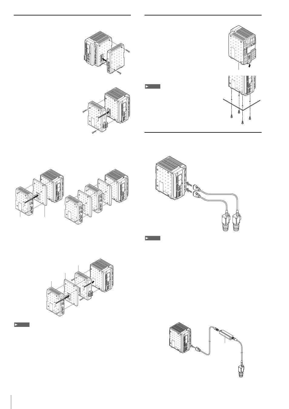
Installing the Expansion Unit
Installing the Camera Expansion Unit (CV-5701/5501 only)
Use the camera expansion unit
CV-E500 (sold separately) to connect
three or more cameras.
Remove the protective connector
cover from the right side of the
controller and install the camera
expansion unit as shown below.
Installing the Communication Expansion Unit
The optional CC-Link expansion unit
CA-NCL10E is used when
communicating with CC-Link devices.
Remove the protective cover of
connector 2 from the left side of the
controller and install the CC-Link
expansion unit.
Installing the Illumination Expansion Unit
Up to 4 CA-DC21E unit may be connected for control of up to 8
individual lighting units. Remove the protective cover of connector 2
from the left side of the controller and install the illumination
expansion unit as shown below.
When using the illumination expansion unit and CC-Link unit
simultaneously
Mount the CC-Link unit CA-NCL10E directly to the controller, then
mount the illumination expansion unit to the left side of the CC-Link
unit.
• Turn off the power to the controller when connecting or removing an each
expansion unit. Connecting or removing the each expansion unit while the
power is being supplied may damage the controller or peripheral devices.
• When a expansion unit is not connected, place the connector protection
cover back on the controller. Using the controller with the connector
exposed may cause damage to the controller.
• It is necessary to mount the supplied attachments before mounting the
illumination expansion unit. The main unit and the illumination expansion
unit can be damaged if the supplied attachments are not mounted.
Installing the CV
Installing the Controller on a DIN Rail
The controller unit and the expansion unit
are designed to be mounted on a DIN rail.
Pull out the tab on the bottom in the
direction of the arrow to mount or dismount
the controller.
Mounting to the Bottom of the Controller
Mount the controller in a stable location that is free
from vibration.
Connecting the Camera Cables
Connect the camera to the camera connector of the controller unit
using one of the optional camera cables.
If connecting only a single camera, attach it to the camera 1 connector.
• Bundle cables with a spiral tubing material. Direct bundling will concentrate
the cable load on the bindings, which can result in cable damage or short
circuit.
• In the absence of other specifications, the minimum cable flexibility (R)
should be 3 times the external diameter (5 times is recommended).
Additionally, repeated curvature and screw stress should be avoided. The
minimum flexion is the same, even when using flexible cable. Unless
otherwise stated, use R100 or greater.
• Camera cable CA-CN17, CA-CN17L, and CA-CN17R can only be
connected to the CV-035C and CV-035M.
• High speed camera CV-H**** can only be connected to the camera cable of
CA-CH*.
• It may cause a damage or malfunction if the camera cable is connected to
the other camera, so do not connect the wrong camera cable.
Using the repeater for camera cable extension
The camera cable can be extended by using the extension repeater
for the camera cable.
When connecting
multiple units
OUT
IN
PO
WER
LIGHT 2
4
3
2
1
LIGHT 1
4
3
2
1
OUT
IN
PO
WER
LIGHT 2
4
3
2
1
LIGHT 1
4
3
2
1
Attachment
(supplied with illumination
expansion unit)
Illumination
expansion unit
OUT
IN
PO
WER
LIGHT 2
4
3
2
1
LIGHT 1
4
3
2
1
OUT
IN
PO
WER
LIGHT 2
4
3
2
1
LIGHT 1
4
3
2
1
Attachment
(supplied with the illumination
expansion unit)
Illumination expansion unit
CA-DC20E
CC-Link unit CA-NCL10E
Note
Tab
M4 screws
Note
To camera 1 connector
To camera 2 connector
CAM2
CAM1
Note
Camera cable
extension repeater