Identifying controls and connectors, Installing the controller unit, Caution on direction of controller mounting – KEYENCE CV-5001 Series User Manual
Page 3
3
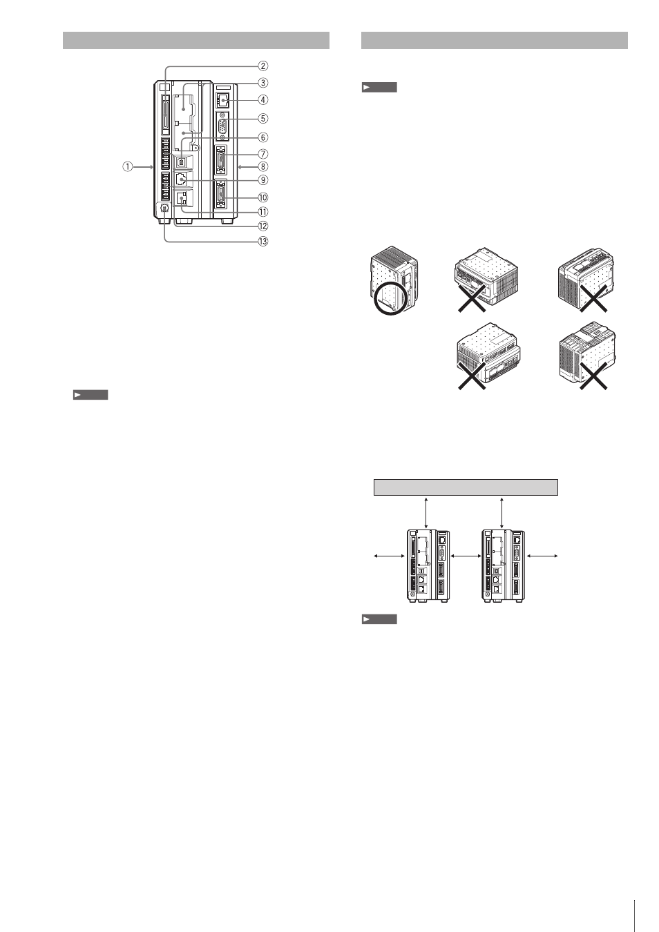
1 Expansion unit connector 2 (left side)
Use to connect the illumination expansion unit CADC21E or
CC-Link unit CA-NCL10E.
2 Parallel I/O connector
Use to connect the parallel input/output signals.
3 SD2 slot (upper), SD1 slot (lower)
Insert an SD card.
The lower slot (SD1) holds the included SD Card (512 MB or 1
GB) by factory default.
SD Card 1 must be inserted while the device is operating.
4 Modular connector
Use to connect the remote control console.
5 RGB output terminal (SVGA)
Use to connect to an external monitor.
6 USB port
Use to connect to the USB cable.
7 Camera 2 connector
Use to connect camera 2.
8 Expansion unit connector 1 (right side, only for CV-5701/
5501)
Use to connect the camera expansion unit CV-E500.
9 RS-232C port
Use to connect to the RS-232C communication cable.
10Camera 1 connector
Use to connect camera 1.
11Ethernet connector
Use to connect the Ethernet cable.
12Terminal Block I/O connector
Use to connect the power supply (24 V DC) and the input/output
signals.
13Grounding terminal
Use to connect the installation line.
Install the controller unit to DIN rail, or use the holes on the bottom of
the controller to secure it with screws.
• Do not install the CV in a location with lots of dust or water vapor. The CV
does not have a mechanism to protect the CV from dust or water. Dust or
water entering the controller can cause damage to the CV.
• Turn off the power to the controller when connecting or removing an
expansion unit, a cable, or a terminal block. Connecting or removing the
camera expansion unit, the cable, or the the terminal block while the power
is being supplied may damage the controller or peripheral devices.
• When a expansion unit is not connected, place the connector protection
cover back on the controller. Using the controller with the connector
exposed may cause damage to the controller.
Caution on Direction of Controller Mounting
• Install the controller in the direction indicated by the circle as
shown below. Do not install the controller in any other direction.
• For ventilation, keep the space free of objects for 50 mm or more
above the controller and 50 mm or more for both sides. Keep the
space free of objects for 90 mm or more in the front of the
connector panel to connect the cables safely.
• When two or more controllers are installed side by side, keep the
space free of objects for 50 mm or more between controllers, and
50 mm or more on top of both controllers.
• Do not block the ventilation openings on the top and bottom of the
controller. If the vents are blocked, heat is accumulated inside the machine
and can cause system failure.
• If the temperature inside the control panel (temperature at the bottom of the
controller) exceeds the rating, use forced air-cooling or increase the free
space around the system to improve ventilation until the operating ambient
temperature drops below the rating.
Identifying Controls and Connectors
Note
Installing the Controller Unit
Note
50 mm
50 mm
50 mm
50 mm
50 mm
Note