Common specifications, Checklist, Sl-v-im-e – KEYENCE SL-V Series User Manual
Page 9
9
SL-V-IM-E
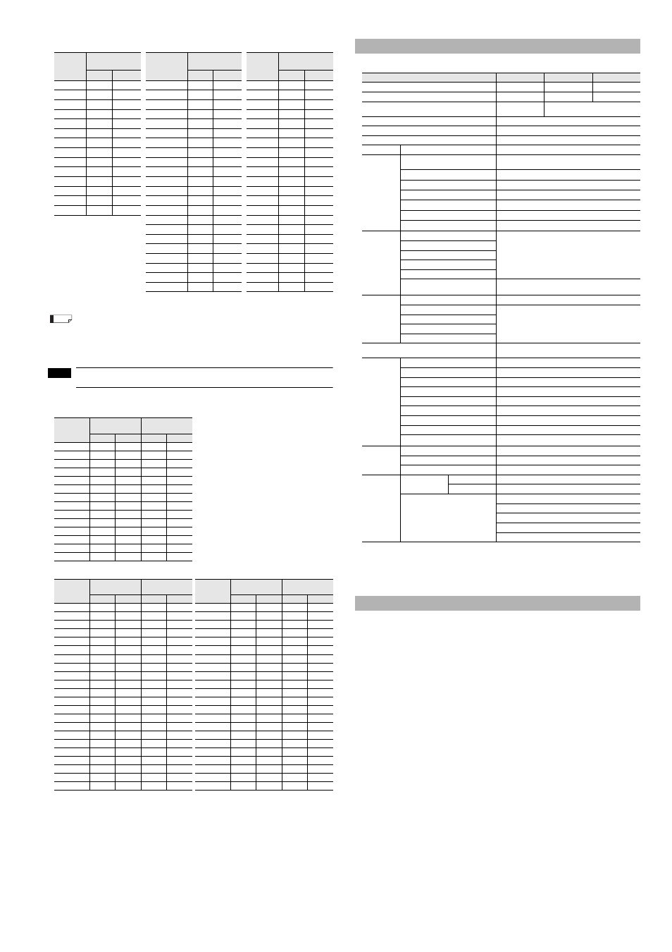
Response time
Units: ms
Units: ms
Units: ms
*1 If the interruption is present in the detection zone for less than 80 ms, the response time (OFF to ON) is to be 80ms or
more to ensure that the OSSD keeps OFF state for more than 80 ms.
When connecting the SL-V units in series, the response time (ON to OFF) is the sum of the response
times of all the individual SL-V units.
When connecting the SL-V32H (32 beam axes), SL-V24H (24 beam axes), and SL-V12L (12 beam
axes) in series, the response time of each unit is 10.3 ms, 9.2 ms, and 7.6 ms respectively, and the
response time (ON to OFF) is 10.3 ms + 9.2 ms + 7.6 ms = 27.1 ms.
the response time (OFF to ON) is 27.1 ms + 40ms = 67.1 ms.
1.6 m/s is the maximum speed of movement of the test piece to which the detection capability is maintained.
Current consumption
Unit: mA
Unit: mA
Unit: mA
*1
When the SL-V is used under surrounding air temperatures between 45 to 55
°C, the Maximum load current should not
exceed 300 mA.
*2
Applies to situations when power is either off or disconnected.
*3
The wiring resistance between the OSSD output and the connected equipment (excluding the resistance of the cable)
must be 2.5 ohms or less to ensure operation. If the cable length is 15 m or more and the load’s current consumption is
200 mA or more, the wire resistance must be 1 ohm or less.
*4
When operating in surrounding air temperatures ranging from 45 to 55
°C, use incandescent lamps (24 VDC, 1 to 3 W)
or LED lamps (load current:10 to 100 mA)
You are fully responsible for performing the risk assessment on your machine application, taking into
account performing maintenance and inspections, which are critical factor for appropriate risk
assessment. In addition, it is a responsibility for the responsible personnel to train the machine oper-
ators regarding inspection and maintenance of the machine and the SL-V.
Inspection before operation (Initial inspection)
When the installation of the SL-V is completed, the responsible personnel must verify the operation of
the SL-V in accordance with the checklist shown below. Note that the following inspection items com-
prise only a bare minimum inspection. KEYENCE Corporation strongly recommends including the nec-
essary checking items into this checklist based on the judgment of the responsible personnel since
additional criteria may be necessary depending on both the machine to which the SL-V is installed and
the laws, rules, regulations and standards in the country or region in which the SL-V is used/installed.
(1) Pre-check for installation condition
•
The machine under SL-V control can be caused to stop running by the OFF-state of OSSD.
•
The SL-V is installed so that the machine operator cannot go into or approach the hazardous area
without passing through the detection zone.
•
The interlock reset mechanism is installed so that it cannot be operated if there are any personnel
within the hazardous area.
•
The device to activate the override is installed so that it cannot be operated if there are any per-
sonnel within the hazardous area.
•
The SL-V has been installed at a distance greater than or equal to the minimum safety distance required.
•
If there are glossy surfaces nearby, move them so that they are beyond the minimum installation
distance according to "Installation Distance From Glossy Surfaces".
•
The SL-V is installed at a location free from light interference, for example fluorescent lamps.
•
The transmitters and receivers are paired correctly.
•
The beam axis spacing (detection capability) is the same between the transmitter and the
receiver when installing the SL-V.
•
The muting devices fulfill the conditions specified in this instruction manual and the requirements of the laws,
rules, regulations and standards in the country or region in which the SL-V and those devices are used.
•
The devices used to activate the override fulfill the conditions specified in this manual and
requirements of the laws, rules, regulations and standards in the country or region in which the
SL-V and those devices are used.
Model
Response time
(OSSD)
Model
Response time
(OSSD)
Model
Response time
(OSSD)
ON to OFF OFF to ON
*1
ON to OFF OFF to ON
*1
ON to OFF OFF to ON
*1
SL-V23F/FM
9.1
49.1
SL-V08H
7
47
SL-V04L
6.5
46.5
SL-V31F/FM
10.2
50.2
SL-V12H/HM
7.6
47.6
SL-V06L/LM
6.8
46.8
SL-V39F/FM
11.3
51.3
SL-V16H/HM
8.1
48.1
SL-V08L/LM
7
47
SL-V47F/FM
12.4
52.4
SL-V20H/HM
8.7
48.7
SL-V10L/LM
7.3
47.3
SL-V55F/FM
13.5
53.5
SL-V24H/HM
9.2
49.2
SL-V12L/LM
7.6
47.6
SL-V63F/FM
14.6
54.6
SL-V28H/HM
9.8
49.8
SL-V14L/LM
7.8
47.8
SL-V71F/FM
15.7
55.7
SL-V32H/HM
10.3
50.3
SL-V16L/LM
8.1
48.1
SL-V79F/FM
16.8
56.8
SL-V36H/HM
10.9
50.9
SL-V18L/LM
8.4
48.4
SL-V87F/FM
17.9
57.9
SL-V40H/HM
11.4
51.4
SL-V20L/LM
8.7
48.7
SL-V95F/FM
19
59
SL-V44H/HM
12
52
SL-V22L/LM
8.9
48.9
SL-V103F/FM
20.1
60.1
SL-V48H/HM
12.5
52.5
SL-V24L/LM
9.2
49.2
SL-V111F/FM
21.2
61.2
SL-V52H/HM
13.1
53.1
SL-V26L/LM
9.5
49.5
SL-V119F/FM
22.3
62.3
SL-V56H/HM
13.6
53.6
SL-V28L/LM
9.8
49.8
SL-V127F/FM
23.4
63.4
SL-V60H/HM
14.2
54.2
SL-V30L/LM
10
50
SL-V64H/HM
14.7
54.7
SL-V32L/LM
10.3
50.3
SL-V72H/HM
15.8
55.8
SL-V36L/LM
10.9
50.9
SL-V80H/HM
16.9
56.9
SL-V40L/LM
11.4
51.4
SL-V88H/HM
18
58
SL-V44L/LM
12
52
SL-V96H/HM
19.1
59.1
SL-V48L/LM
12.5
52.5
SL-V104H
20.2
60.2
SL-V52L
13.1
53.1
SL-V112H
21.3
61.3
SL-V56L
13.6
53.6
SL-V120H
22.4
62.4
SL-V60L
14.2
54.2
Model
When the center
indicator is ON
When the center
indicator is OFF
Transmitter
Receiver
Transmitter
Receiver
SL-V23F/FM
83
78
80
74
SL-V31F/FM
93
80
90
75
SL-V39F/FM
103
82
99
77
SL-V47F/FM
112
85
107
78
SL-V55F/FM
121
87
115
80
SL-V63F/FM
129
89
122
82
SL-V71F/FM
136
92
129
83
SL-V79F/FM
142
94
135
85
SL-V87F/FM
148
97
140
87
SL-V95F/FM
154
99
145
88
SL-V103F/FM
159
101
149
90
SL-V111F/FM
163
104
152
92
SL-V119F/FM
166
106
156
93
SL-V127F/FM
169
109
158
95
Model
When the center
indicator is ON
When the center
indicator is OFF
Model
When the center
indicator is ON
When the center
indicator is OFF
Transmitter
Receiver
Transmitter
Receiver
Transmitter
Receiver
Transmitter
Receiver
SL-V08H
56
70
52
65
SL-V04L
48
70
45
66
SL-V12H/HM
63
72
58
66
SL-V06L/LM
53
71
50
67
SL-V16H/HM
69
74
64
67
SL-V08L/LM
59
72
55
67
SL-V20H/HM
75
75
70
68
SL-V10L/LM
64
74
59
67
SL-V24H/HM
81
77
76
69
SL-V12L/LM
69
75
64
68
SL-V28H/HM
87
79
81
69
SL-V14L/LM
74
76
68
68
SL-V32H/HM
93
80
86
70
SL-V16L/LM
79
77
72
69
SL-V36H/HM
98
82
91
71
SL-V18L/LM
84
78
76
69
SL-V40H/HM
103
84
96
72
SL-V20L/LM
88
80
80
70
SL-V44H/HM
108
85
100
73
SL-V22L/LM
93
81
84
70
SL-V48H/HM
113
87
104
74
SL-V24L/LM
97
82
88
71
SL-V52H/HM
117
88
109
74
SL-V26L/LM
101
83
92
71
SL-V56H/HM
122
90
112
75
SL-V28L/LM
105
84
95
71
SL-V60H/HM
126
91
116
76
SL-V30L/LM
109
86
98
72
SL-V64H/HM
130
93
120
77
SL-V32L/LM
113
87
102
72
SL-V72H/HM
137
96
126
78
SL-V36L/LM
120
89
108
73
SL-V80H/HM
144
98
132
80
SL-V40L/LM
126
91
113
74
SL-V88H/HM
149
101
136
81
SL-V44L/LM
132
93
119
75
SL-V96H/HM
154
104
140
83
SL-V48L/LM
137
95
123
75
SL-V104H
159
107
143
84
SL-V52L
142
97
127
76
SL-V112H
162
109
146
86
SL-V56L
146
99
131
77
SL-V120H
165
112
147
87
SL-V60L
150
101
134
78
Reference
NOTE
Common specifications
Model
SL-VF/SL-VFM
SL-VH/SL-VHM
SL-VL/SL-VLM
Beam axis spacing/Lens diameter
10 mm/
φ4 mm
20 mm/
φ5 mm
40 mm/
φ5 mm
Detection capability
φ14 mm
φ25 mm
φ45 mm
Operating distance
0.1m to 7.0m
0.1m to 9.0m (detection height of 1,260mm or less)
0.1m to 7.0m (detection height of 1,400mm or more)
Effective aperture angle
Max. ±2.5
° (When operating distance is 3 m (9.84 ft.) or more)
Light source
Infrared LED (850 nm)
Operation form
Turns on when no interruptions are present in the detection zone
Rating
Power voltage
24 VDC +10%, -20% (Ripple P-P 10% or less), Class 2
OSSD
Output
2 outputs each for PNP and NPN.
Can be changed by using the connector cable
Max. load current
500 mA
*1
Residual voltage (during ON)
Max. 2.5 V (with a cable length of 7 m (22.97 ft.))
OFF state voltage
Max. 2.0 V (with a cable length of 7 m (22.97 ft.))
Leakage current
Max. 100
μA
*2
Max. capacitive load
1
μF (with a load resistance of 100 Ω)
Load wiring resistance
Max. 2.5
Ω
*3
Non safety-
related output
AUX
Output with automatic PNP/NPN switching function, 50 mA
max.
Interlock-reset-ready output
Alert output
Clear/Blocked Output
State information output 1, 2
Muting lamp output
Incandescent lamp (24 VDC, 1 to 7 W) or LED lamp
(load current :10 to 300 mA)
*4
can be connected
Input
EDM input
Short-circuit current 10 mA
Wait input
Short-circuit current 2.5 mA
Reset input
Muting input 1, 2
Override input
Protection circuit
Reverse current protection, short-circuit protection for each
output, surge protection for each output
Environmental
condition
Enclosure protection
IP65 (IEC60529), IP65/67 (only for SL-VFM,SL-VHM and SL-VLM)
Overvoltage Category
II
Operating ambient temperature
-10 to +55
°C (No freezing)
Storage ambient temperature
-25 to +60
°C (No freezing)
Operating relative humidity
15% to 85%RH (No condensation)
Storage relative humidity
15% to 95%RH
Surrounding light
Incandescent lamp: 5,000 lx or less. Sunlight: 20,000 lx or less
Vibration
10 to 55 Hz, 0.7 mm compound amplitude, 20 sweeps each in X, Y, and Z directions
Shock
100 m/s
2
(Approx. 10 G) 16 ms pulse, in X, Y, Z directions 1,000 times each axis
Material
Main unit case
Aluminum
Upper case/Lower case
Zinc die-cast
Front cover
Polycarbonate, SUS304
Approved
standards
EMC
EMS
IEC61496-1, EN61496-1, UL61496-1
EMI
EN55011 ClassA, FCC Part15B ClassA, ICES-003 Class A
Safety
IEC61496-1, EN61496-1, UL61496-1 (Type 4 ESPE)
IEC61496-2, UL61496-2, EN61496-2 (Type 4 AOPD)
IEC61508, EN61508 (SIL3), IEC62061, EN62061 (SIL3)
EN ISO13849-1:2008 (Category 4, PL e)
UL508, UL1998
Checklist