Example for wiring, Caution, Sl-v-im-e – KEYENCE SL-V Series User Manual
Page 5
5
SL-V-IM-E
When using the muting bank function
• The shielding wire of the PNP output type cable is connected to 0 V line in the SL-V.
Do not connect the shielding wire to +24 V line.
• The shielding wire of the NPN output type cable is connected to +24 V line in the SL-V.
Do not connect the shielding wire to 0 V line.
• When not using a non safety-related output, insulate the wires.
When using a simple function type cable (Automatic start/reset mode, When
not using the EDM function)
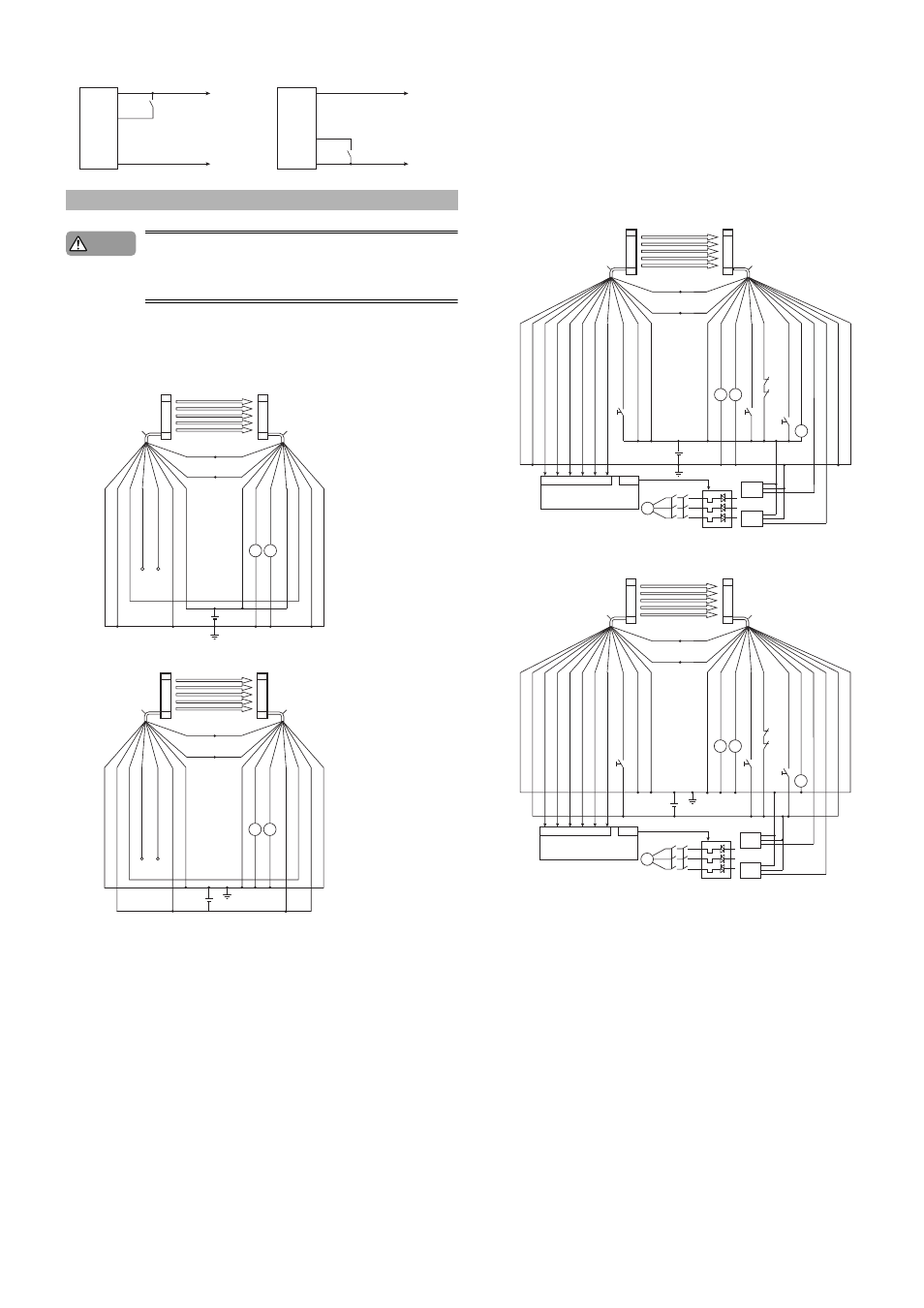
Meaning of symbols
K1, K2: External device (Safety relay unit, etc.)
PNP output type cable
NPN output type cable
When using a multi-function type cable (Other than automatic start/reset mode,
When using the EDM function)
Meaning of symbols
K1, K2: External device (Safety relay unit, magnet contactor, etc.)
K3
: Solid state contactor
*1
S1
: The switch for wait input (N.O.)
*1
The violet wire needs to be capped it is not used. (Open circuit : completely discon-
nected)
S2
: The switch for reset input (N.O.)
S3
: The switch for override input (N.O.)
L1
: Muting lamp (Incandescent lamp or LED lamp)
P1, P2 : Muting device (PZ self-contained photoelectric sensors, etc.)
M
: 3-phase motor
PLC
: For the monitoring use
*1
*1 These are NON SAFETY-RELATED system.
PNP output type cable
NPN output type cable
Example for Wiring
Brown
Blue
Muting bank input 1 (purple)
Muting bank input 2 (red/black)
Muting bank input 3 (pink)
Short-circuit current: 2.5mA
Transmitter
or
receiver
Main
circuit
0 V
+24 V
Brown
Blue
Muting bank input 1 (purple)
Muting bank input 2 (red/black)
Muting bank input 3 (pink)
Short-circuit current: 2.5mA
Transmitter
or
receiver
Main
circuit
0 V
+24 V
When using a PNP output type cable
When using an NPN output type cable
Caution
Cable insulation: Black
Cable insulation: Grey
Transmitter
Receiv
er
(Inter
loc
k-reset-ready output) Green
(+24 V)
Bro
wn
(+24 V)
Bro
wn
(OSSD2) White
(OSSD1) Blac
k
(Reset input)
Y
ello
w
(EDM input) Red
(W
ait input)
Violet
(A
UX output) Red
(0 V)
Blue
(0 V)
Blue
Shield
Shield
K2
K1
(Inter
loc
k mode selection input) Pink
Orange/black
(Communication cable 2)
Orange
(Communication cable 1)
S1
S2
S3
K1
K2
K2
K3
K2
K1
M
IN
PLC
OUT
K1
L1
P 1
P 2
(Inter
loc
k mode selection input) Pink
Cable insulation: Black
Cable insulation: Grey
Transmitter
Receiv
er
(Inter
loc
k-reset-ready output) Green
(+24 V)
Bro
wn
(+24 V)
Bro
wn
(OSSD2) White
(OSSD1) Blac
k
(Reset input)
Y
ello
w
(EDM input) Red
(Ov
err
ide input) Red/b
lac
k
(Muting lamp output)
Y
ello
w/b
lac
k
(Muting input 1) Light b
lue
(Muting input 2) Light b
lue/b
lac
k
(W
ait input)
Violet
(A
UX output) Red
(State inf
or
mation output 1) Gre
y
(State inf
or
mation output 2) Gre
y/b
lac
k
(Aler
t output) Pink/b
lac
k
(Clear/Bloc
k
ed output)
White/b
lac
k
(0 V)
Blue
(0 V)
Blue
Shield
Shield
Orange/black
(Communication cable 2)
Orange
(Communication cable 1)
Brown
Brown
Blue
Blue
Black
Black
Use PNP output type for P1 and P2.
S1
S2
S3
K1
K2
K2 K1
L1
P 1
P 2
K3
K2
K1
M
IN
PLC
OUT
Cable insulation: Black
Cable insulation: Grey
Transmitter
Receiv
er
(Inter
loc
k-reset-ready output) Green
(Inter
loc
k mode selection input) Pink
(+24 V)
Bro
wn
(+24 V)
Bro
wn
(OSSD2) White
(OSSD1) Blac
k
(Reset input)
Y
ello
w
(EDM input) Red
(Ov
err
ide input) Red/b
lac
k
(Muting lamp output)
Y
ello
w/b
lac
k
(Muting input 1) Light b
lue
(Muting input 2) Light b
lue/b
lac
k
(W
ait input)
Violet
(A
UX output) Red
(State inf
or
mation output 1) Gre
y
(State inf
or
mation output 2) Gre
y/b
lac
k
(Aler
t output) Pink/b
lac
k
(Clear/Bloc
k
ed output)
White/b
lac
k
(0 V)
Blue
(0 V)
Blue
Shield
Shield
Brown
Brown
Blue
Blue
Black
Black
Orange/black
(Communication cable 2)
Orange
(Communication cable 1)
Use NPN output type for P1 and P2.