Center indicator, Sl-v configurator (sl-vh1s), Temporary suspension of safety function – KEYENCE SL-V Series User Manual
Page 7: Nomenclature, Sl-v-im-e
7
SL-V-IM-E
Receiver
*1
For the interval of blinking, lights for 2 seconds, and turns off for 0.3 seconds. In other cases, lights for 0.3 seconds and
also turns off for 0.3 seconds.
SL-VH
When the SL-V Configurator is used, the following setting changes and functions are available.
*1 For details, refer to "Temporary Suspension of Safety Function".
*2 When setting the interlock function not with the SL-V Configurator but only with wiring, two types of
settings are available: manual for both start and restart, or automatic for both start and restart.
Muting Function
The muting function is used to temporarily suspend the SL-V's safety functions while the SL-V receives a
signal from muting devices (such as sensors or switches). Before this function can be used, the outputs
from the muting devices must be connected to the muting input terminal on the SL-V.
In addition, the SL-V Configurator (SL-VH1S) provides the user with the opportunity to select the beam
axes to be muted condition. You can minimize the number of beam axes to be muted condition by using
SL-VH1S. Therefore, you can reduce a risk of approaching into hazardous zone accordingly.
Muting device
When using the muting device, it must be met with the following conditions.
• The muting device output must be N.O. (normal open).
• Output of the muting device must be the output with contacts, and must be PNP output type if
PNP output type cable is used, or NPN output type if NPN output type cable is used. Also, the
muting device must be capable of 2 to 3mA current.
• Do not use one muting device with multiple outputs in place of two or more muting devices.
(Only one output per one muting device must be used.)
• If the muting device has a timer function that can adjust the output timing, do not use that
function.
Muting lamp
When using the muting lamp, it must meet the following conditions.
For an incandescent lamp
: rated 24 V DC, 1 to 7 W
For LED indicator
: rated current consumption must be 10 to 300 mA.
If the incandescent lamp burns out, or if the lamp used does not meet the above conditions, the
state information output shows a muting lamp error.
Conditions for initiation of muting
Muted condition is initiated if all of the following conditions are met.
• Muting input 2 turns ON within 0.04 to 3 seconds after muting input 1 turns ON
• SL-V detects no interruption in the detection zone
• OSSD is ON state and keeps staying for 0.5 seconds or more.
Conditions for termination of muting
Muted condition is terminated if one of the following conditions is met.
• Either of muting inputs goes to OFF state at least for more than 0.02 sec.
• Light curtain goes to lockout condition
• Wait input goes to ON state
• The power supply is interrupted or restored.
• Maximum muting period of approx. 5 minutes has been passed.
Changing of conditions for muting
The following muting conditions can be changed through the SL-V Configurator (SL-VH1S) or the
special procedures.
Condition for Initiation of muting
1. Time period specification of 0.04s to 3s between muting input 1 and muting input 2 can be
option.
2. Sequence specification of muting inputs can be option. (Default sequence: muting input 1 is
first, muting input 2 is second.)
Condition for termination of muting
3. Maximum muting period of approx. 5 minutes can be option.
Condition for muting lamp
4. Lockout condition can be initiated if muting lamp has some failure.
If you choose these options according to your machine application, password setting and/or pass-
word input is required as a special procedure.
The responsible personnel who intends to apply these options mentioned above from 1 to 3 have to
perform the risk assessment based on the machine application.
Muting bank function
The muting bank function can be activated through the SL-V Configurator (SL-VH1S).
You can configure the muting bank, which is a group of the beam axes that will become muted condi-
tion in case of activation of muting.
SL-V can have three of muting banks.
In order to select the muting bank to be activated, you have to switch (ON and OFF) the muting bank
input.
Override function
The OSSD goes to an OFF state if the muting function is deactivated and an interruption remains in
the detection zone of the SL-V. The OSSD OFF state will remain until the obstruction is removed.
The override is a function to allow a temporary manual suspension of the SL-V safety functions.
This makes it possible to remove the obstruction remaining in the detection zone of the SL-V.
(Machine is able to be manually operated on a temporary basis because the safety function of the
SL-V is temporarily suspended.)
Conditions for initiation of override
Override function is initiated if all of the following conditions are met and the reset input goes to
ON state within 0.04s to 1s after override input turns ON state.
• SL-V is not in the lockout condition.
• SL-V detects interruption in the detection zone. (One or more beam axis is blocked.)
• OSSD is OFF state. (including interlock condition)
• Either of muting inputs, or both, turns ON state
Conditions for termination of override
Override function is terminated if one of the following conditions is met.
• All of muting inputs turns OFF state.
• Either override input or reset input, or both, turns OFF state.
• Wait input turns ON state.
• Light curtain goes to lockout condition
• Maximum override period of approx. 60 seconds has been passed.
Changing of the condition for override
The following condition can be changed through the SL-V Configurator (SL-VH1S).
Conditions that deactivate the override condition
• Maximum override period of approx. 60 seconds can be option.
If you choose this option according to your machine application, password setting and/or password
input is required. The responsible personnel must securely manage the password. The responsible
personnel who intends to apply this option must perform the risk assessment based on the machine
application.
(1) Basic designation
: SL-V
(2) The number of beam axes
Example
: "08" means
→ 8 axes, "64" means → 64 axes
(3) Detection capability
F
:
φ
14 mm
H
:
φ
25 mm
L
:
φ
45 mm
(4) Enclosure type
No symbol
: General-purpose model
M
: with rigid enclosure
(5) Unit type
T
: Transmitter
R
: Receiver
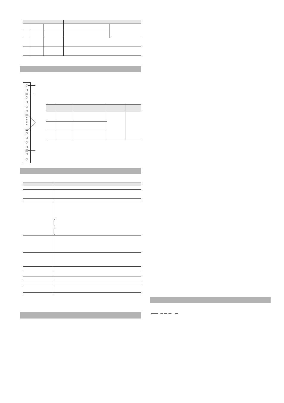
Indicators
Description
(1)
MUTE 1
Muting indicator 1
Blinking in orange
Light OFF
: Muting device 1 ON
: Muting device 1 OFF
Both MUTE1 and MUTE2 light
in orange during muted
condition. Both MUTE1 and
MUTE2 slowly blink
*1
in orange
during the override condition.
(2)
MUTE 2
Muting indicator 2
Blinking in orange
Light OFF
: Muting device 2 ON
: Muting device 2 OFF
(3)
OSSD
OSSD indicator
Light in green
Light in red
Light OFF
: OSSD ON
: OSSD OFF
: Power turned OFF
(4)
INTER
LOCK
Interlock indicator
Light in yellow
Blinking in yellow
Light OFF
: Interlock condition
: Lockout condition
: Neither interlock condition nor lockout condition
Center Indicator
SL-V Configurator (SL-VH1S)
Items
Description
Muting function
*1
You can select the beam axes to be muted. The muting conditions can also be changed.
Muting bank function
*1
You can change the setting whether or not to use the Muting bank function.
When the muting bank function is used, the override function is disabled. Set the interlock function
with the SL-V Configurator because setting of the interlock function with wiring is disabled.
Override function
*1
You can change the override condition.
Interlock function
*2
The Interlock function enables OSSD to hold the OFF-state if no interruptions are present in
the detection zone upon startup (when the power turns on or the lockout error condition is
terminated by the reset input) or upon restart (when the SL-V is interrupted and the OSSD
becomes the OFF-state). This state is called "interlock ". To recover from the interlock
condition, the reset input must be switched ON to OFF while no interruptions are present in
the detection zone. Automatic or manual can be selected individually for start and restart.
Automatic start : The OSSD automatically enters the ON-state when no interruptions are
present in the detection zone.
Manual start
: Enters interlock condition upon startup.
Automatic reset : The OSSD automatically returns to the ON-state when no interruptions
are present in the detection zone.
Manual reset
: Enters interlock condition upon restart.
Fixed blanking function
This function is enabled only for the specified beam axes. The OSSD can hold the ON-
state even when an interruption is present in the area. A desired area can be set as an
effective zone of this function on a pair of transmitter and the receiver as well as on the all
beam axes including the SL-V connected in series. The area where this function is enabled
can be set as desired not only between a transmitter-receiver pair, but also on all the beam
axes including the SL-V connected in series.
Reduced resolution function
The OSSD holds the ON-state when the object is blocking only a specified number of
beam axes (one beam axis to the half of all axes can be set), and the OSSD turns OFF only
when the object is blocking more beam axes than the specified number. This function is
effective not only for a transmitter-receiver pair, but also all the beam axes including the
SL-V connected in series.
Center indicator
You can change the conditions for the center indicator to turn on, off, or blink.
EDM function
You can change the setting whether or not to use the EDM function. The tolerance time of
the EDM input can also be changed.
State information output
You can change the output methods and the pulse time of the state information output.
Emitting cycle change
You can change the laser emission cycle. The SL-V units with different laser emission cycle
can reduce the chance of mutual interference.
Alert output monitoring time
change
You can change for how many seconds the unstable clear state can continue before
issuing an alert output (alert output monitoring time).
Monitor function
You can monitor the received light intensity of each beam axis on the SL-V.
Temporary Suspension of Safety Function
Beam axis
Center
indicator
(Upper)
Center
indicator
(Lower)
Center
indicator
(Middle)
Center indicator (Upper) : indicates whether interruption is present in the top
beam axis or not. (clear or blocked)
Center indicator (Middle) : indicates whether the middle axis beams are interrupted
or not. The SL-V08H(S) and SL-V04L do not have this
indicator.
Center indicator (Lower) : indicates whether interruption is present in the bottom
beam axis or not. (clear or blocked)
Center
indicator
Light OFF
red light
green light
Blinking red
light
Upper
Top beam axis
is blocked
Although the top beam axis is
unblocked, the others are
blocked
No interruption is
present in
detection zone of
the SL-V. (clear)
Lockout
condition
Middle
Middle beam
axis are
blocked
Although the top and bottom
beam axis are unblocked, the
middle beams are blocked
Lower
Bottom beam
axis is blocked
Although the bottom beam axis is
unblocked, the others are
blocked
Nomenclature
SL-V 12 H M - T
(1)
(2) (3) (4)
(5)