Installation measures against glossy surface, Ossd circuit diagram, Wiring and function – KEYENCE SL-V Series User Manual
Page 4: Sl-v-im-e, Ossd circuit diagram wiring and function
4
SL-V-IM-E
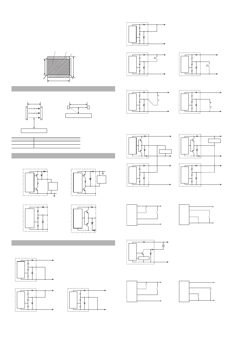
Detection zone
: The zone in which the specified detection capability can be detected. The
detection zone of the SL-V indicates a square area formed with the detection
height and the operating distance. When a part or whole of the specified detec-
tion capability is present in this area, the light of the SL-V is blocked, and then
the OSSD goes to OFF state.
Protection zone
: The square area formed with the protection height and the operating distance,
which is broader than the detection zone. When a whole of the specified detec-
tion capability is present in this area, the light of the SL-V is blocked, and then
the OSSD goes to OFF state.
* Refer to the following diagram for detection zone and protection zone.
When determining a specific installation distance, refer to the following values including the installa-
tion tolerance.
Wiring for automatic start/automatic reset mode
Wiring other than automatic start/automatic reset mode
Wiring for EDM function
Wiring unless EDM function is applied
When the EDM is not applied through the SL-V Configurator (SL-VH1S), the EDM input should not be
connected to the AUX output (keep open-circuit).
Wiring for muting device
Wiring for muting lamp
Wiring for Override function
Installation measures against glossy surface
Operating distance “X”
Minimum installation distance ”Y”
Less than 3 m
0.13 m
3 m or more
X/2 x tan5
°
= 0.0437 X
OSSD circuit Diagram
Wiring and Function
Protection
height
Specified detection capability
Protection zone
Operating distance
Detection zone
Detection
height
Transmitter
Receiver
5
o
Mirror surface
X
Y
Mirror surface
X
Y
T
ransmitter
Receiv
er
External
device
Main
circuit
+24 V
0 V
10
OSSD
Ω
10
Ω
External
device
Main
circuit
+24 V
0 V
OSSD
Main
circuit
+24 V
0 V
Input
Output
Main
circuit
+24 V
0 V
OSSD PNP output circuit
OSSD NPN output circuit
Input circuit
Output circuit
Receiver
Main
circuit
Blue
Brown
Yellow (reset input)
0 V
+24 V
Receiver
Main
circuit
Blue
Brown
Yellow (reset input)
0 V
+24 V
0 V
+24 V
Transmitter
Main
circuit
Blue
Brown
Pink (interlock mode selection input)
Common for a PNP/NPN output type cable
When using a PNP output type cable
When using an NPN output type cable
Blue
Brown
Yellow (reset input)
Short-circuit
current: 2.5 mA
Receiver
Main
circuit
0 V
+24 V
Blue
Pink (interlock mode selection input)
Brown
Transmitter
Main
circuit
0 V
+24 V
Common for a PNP/NPN output type cable
When using a PNP output type cable
Receiver
Main
circuit
Blue
Brown
Yellow (reset input)
Short-circuit
current: 2.5 mA
0 V
+24 V
When using an NPN output type cable
Red
Brown
Short-circuit
current: 10mA
Device 1
Device 2
Blue
Receiver
Main
circuit
0 V
+24 V
Red
Brown
Short-circuit
current: 10mA
Device 1
Device 2
Blue
Receiver
Main
circuit
0 V
+24 V
When using a PNP output type cable
When using an NPN output type cable
Red (AUX output)
Input device
Brown
Blue
Transmitter
Main
circuit
Red (EDM input)
Brown
Blue
Receiver
Main
circuit
0 V
+24 V
0 V
+24 V
0 V
+24 V
Red (EDM input)
Brown
Blue
Receiver
Main
circuit
Input device
Brown
Red (AUX output)
Blue
Transmitter
Main
circuit
0 V
+24 V
When using a PNP output type cable
When using an NPN output type cable
Light blue
Brown
Blue
Light blue/
Black
Receiver
(Muting input 2)
(Muting input 1)
Muting device 1
Muting device 2
Short-circuit current: 2.5 mA
Main
circuit
0 V
+24 V
Brown
Blue
Light blue
Light blue/Black
(Muting input 2)
(Muting input 1)
Receiver
Muting device 1
Muting device 2
Short-circuit current: 2.5 mA
Main
circuit
0 V
+24 V
When using a PNP output type cable
When using an NPN output type cable
Yellow/Black
Muting
lamp
Brown
Blue
Monitor circuit
Main
circuit
Receiver
0 V
+24 V
Common for a PNP/NPN output type cable
Yellow
Brown
Blue
Red/Black
(Override input)
(Reset input)
Receiver
Main
circuit
Short-circuit current: 2.5mA
0 V
+24 V
Brown
Blue
Yellow
Red/Black
(Override input)
(Reset input)
Short-circuit current: 2.5mA
Receiver
Main
circuit
0 V
+24 V
When using a PNP output type cable
When using an NPN output type cable