Dimensions and specifications, Sl-v-im-e – KEYENCE SL-V Series User Manual
Page 8
8
SL-V-IM-E
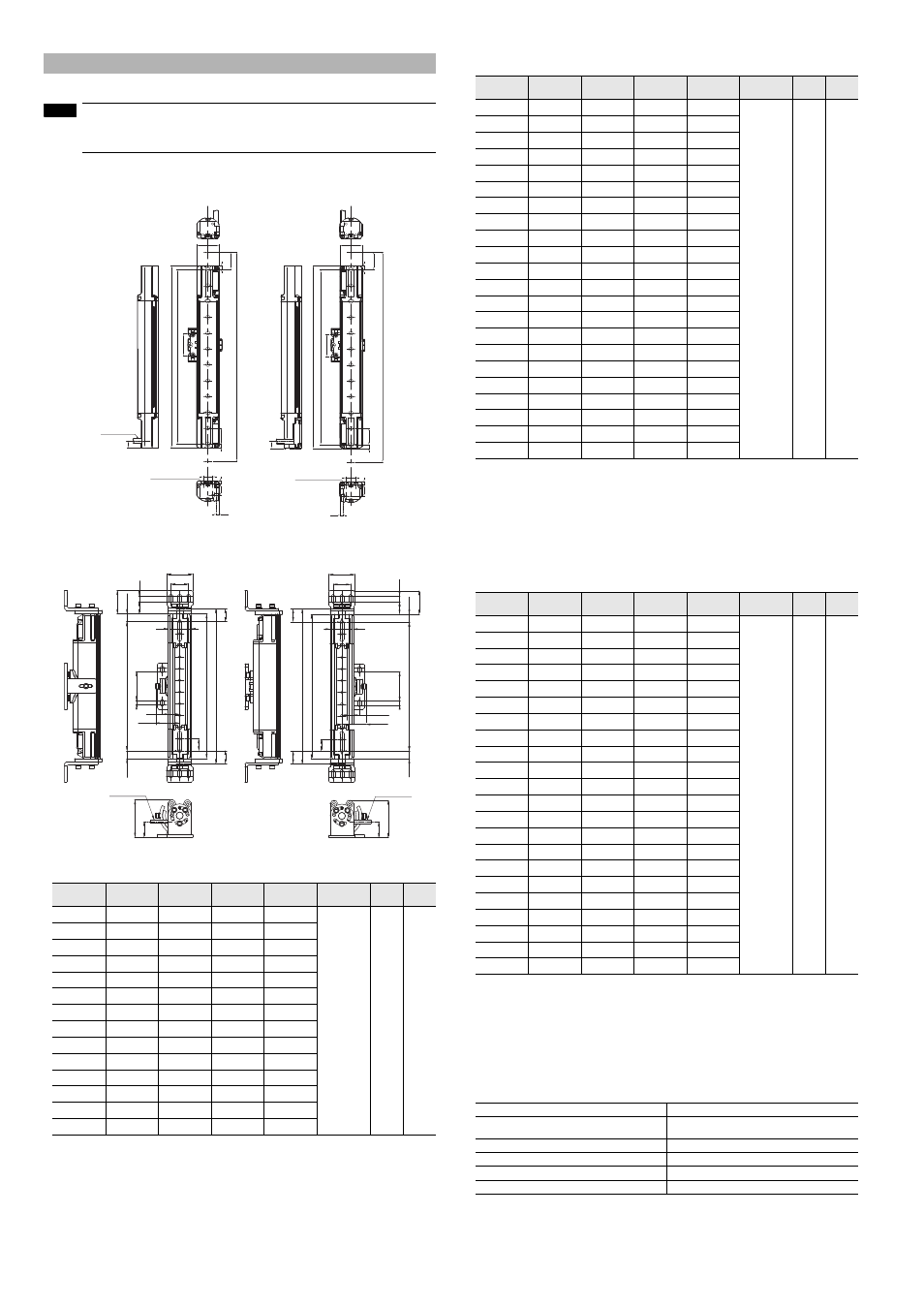
If the length for a single SL-V unit is 710 mm or greater, use a compact E-to-E mounting bracket or an
E-to-E mounting bracket additionally as an intermediate support bracket. The following figures show the
example for the use of one compact E-to-E bracket or space-saving bracket.
For SL-VF, SL-VH, and SL-VL
Units: mm
For SL-VFM, VHM, and VLM
Units: mm
SL-VF
Units: mm
SL-VFM
The following value is the dimension of SL-VFM.
A: Length
Length of the SL-VF + 16mm
E: 13mm
The remaining values (B: detection capability, C: protection height, D: beam axis spacing, and F) are
identical with the dimension of SL-VF.
SL-VH
Units: mm
SL-VHM
The following value is the dimension of SL-VHM.
A: Length
Length of the SL-VH + 16mm
E: 13mm
The remaining values (B: detection capability, C: protection height, D: beam axis spacing, and F) are
identical with the dimension of SL-VH.
SL-VL
Units: mm
SL-VLM
The following value is the dimension of SL-VLM.
A: Length
Length of the SL-VL+ 16mm
E: 33mm
The remaining values (B: detection capability, C: protection height, D: beam axis spacing, and F) are
identical with the dimension of SL-VL.
Parameter for IEC61508
*1 For PFHd of each SL-V, contact your nearest KEYENCE office.
Dimensions and Specifications
Model
Beam axes
A: Length
B: Detection
height
C: Protection
height
D: Beam axis
spacing
E
F
SL-V23F
23
230
220
244
10
5
12
SL-V31F
31
310
300
324
SL-V39F
39
390
380
404
SL-V47F
47
470
460
484
SL-V55F
55
550
540
564
SL-V63F
63
630
620
644
SL-V71F
71
710
700
724
SL-V79F
79
790
780
804
SL-V87F
87
870
860
884
SL-V95F
95
950
940
964
SL-V103F
103
1030
1020
1044
SL-V111F
111
1110
1100
1124
SL-V119F
119
1190
1180
1204
SL-V127F
127
1270
1260
1284
NOTE
3.9
12
E
A
B
C
D
5
F
14
9
28
4
28
φ5.8 Cable
6-M3 Depth 4.5
3.9
12
A
B
C
D
5
9
28
14
4
E
F
28
6-M3 Depth4.5
Transmitter
Receiver
D
7
50
44.2
40
C
F
F
B
63.8
26.8
13
E
(41.1)
30
40
9.8
21.1
30
A
φ5.8 Cable
50
D
7
B
C
F
F
A
(41.1)
26.8
63.8
13
30
21.1
40
40
E
44.2
30
9.8
φ5.8 Cable
Transmitter
Receiver
Model
Beam axes
A: Length
B: Detection
height
C: Protection
height
D: Beam axis
spacing
E
F
SL-V08H
8
150
140
185
20
5
22.5
SL-V12H
12
230
220
265
SL-V16H
16
310
300
345
SL-V20H
20
390
380
425
SL-V24H
24
470
460
505
SL-V28H
28
550
540
585
SL-V32H
32
630
620
665
SL-V36H
36
710
700
745
SL-V40H
40
790
780
825
SL-V44H
44
870
860
905
SL-V48H
48
950
940
985
SL-V52H
52
1030
1020
1065
SL-V56H
56
1110
1100
1145
SL-V60H
60
1190
1180
1225
SL-V64H
64
1270
1260
1305
SL-V72H
72
1430
1420
1465
SL-V80H
80
1590
1580
1625
SL-V88H
88
1750
1740
1785
SL-V96H
96
1910
1900
1945
SL-V104H
104
2070
2060
2105
SL-V112H
112
2230
2220
2265
SL-V120H
120
2390
2380
2425
Model
Beam axes
A: Length
B: Detection
height
C: Protection
height
D: Beam axis
spacing
E
F
SL-V04L
4
150
120
205
40
25
42.5
SL-V06L
6
230
200
285
SL-V08L
8
310
280
365
SL-V10L
10
390
360
445
SL-V12L
12
470
440
525
SL-V14L
14
550
520
605
SL-V16L
16
630
600
685
SL-V18L
18
710
680
765
SL-V20L
20
790
760
845
SL-V22L
22
870
840
925
SL-V24L
24
950
920
1005
SL-V26L
26
1030
1000
1085
SL-V28L
28
1110
1080
1165
SL-V30L
30
1190
1160
1245
SL-V32L
32
1270
1240
1325
SL-V36L
36
1430
1400
1485
SL-V40L
40
1590
1560
1645
SL-V44L
44
1750
1720
1805
SL-V48L
48
1910
1880
1965
SL-V52L
52
2070
2040
2125
SL-V56L
56
2230
2200
2285
SL-V60L
60
2390
2360
2445
T1 (Proof test interval)
20 years
PFHd (average frequency of a dangerous failure per hour)
*1
With no series connection: 8.2 × 10
-9
or less
With series connection: 1.7 × 10
-8
or less
Hardware fault tolerance
1
Type of element
Type B
Failure response time
Within a response time
Safe state
OSSDs are in OFF-state