KEYENCE SL-M Series User Manual
Page 4
4
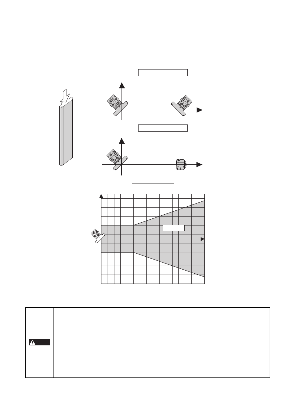
• SL-M Series, GL/SL Series Transmitter or Receiver installation requirements based on the position of the SL-M Series
The following requirement applies only when 2 or more SL-M Series units are being used.
When installing SL-M Series unit at Position A on Graph 2
When 2 of SL-M Series units have been installed as indicated in Definition 2 in the following diagram, no other SL-M Series or GL/SL
Series units can be installed in Area C in Graph 2. In other words, only one SL-M Series unit can be installed in Area C.
When one SL-M Series unit and a GL/SL Series Transmitter or Receiver have been installed as indicated in Definition 3 in the following
diagram, no other SL-M Series or GL/SL Series units can be installed in Area C in Graph 2. In other words, only one GL/SL Series
Transmitter or GL/SL Series Receiver can be installed in Area C. (In this case, you must see “SL-M Series installation requirements
based on the position of the GL/SL Series Transmitter or Receiver” for more information.)
• Failure to follow these requirements may result in a creation of an unexpected hazardous zone allowing human approach,
caused by a misalignment of the installation angles of the GL/SL Series Transmitter, Receiver or the SL-M Series unit. You must
fulfill these requirements when using this system.
• Even if these requirements are not met, these requirements do not apply in the following cases:
- When the installation angle of the GL/SL Series Transmitter/Receiver or the machine where the SL-M Series is installed will
never become misaligned due to their structure, or
- Even if the installation angles happen to accidentally become misaligned, when light emitted from the GL/SL Series
Transmitter cannot be received by the GL/SL Series Receiver due to the structure of the GL/SL Series Transmitter/Receiver
or the machine where the SL-M Series is installed (such as cases where the installation angle has become misaligned but an
object physically blocks positions where the light path may pass).
It is the responsibility of the customer installing the SL-M Series to determine whether the setup is exempted from these
conditions and to take responsibility for the decision. Please understand that Keyence is not responsible for any kind of
problems that occur due to the customer's judgment.
SL-M
Top
SL-M
SL-M
SL-M
Distance X
Transmitter or
Receiver
Distance Y
Distance Y
Distance X
Definition 2 (top view)
Definition 3 (top view)
Graph 2 (top view)
0 0.5 1 1.5 2 2.5 3 3.5 4 4.5 5 5.5 6 6.5 7 7.5
8
(1.64 ft.) (4.92 ft.) (8.20 ft.) (11.48 ft.) (14.76 ft.) (18.04 ft.) (21.33 ft.) (24.61 ft.)
(3.28 ft.) (6.56 ft.) (9.84 ft.) (13.12 ft.) (16.40 ft.) (19.69 ft.) (22.97 ft.) (26.25 ft.)
1000 ( 39.37")
900
(
35.43")
800
(
31.50")
700
(
27.56")
600
(
23.62")
500
(
19.68")
400
(
15.74")
300
( 11.81")
200
( 7.87")
100
( 3.94")
0
-100 ( -3.94")
-200 ( -7.87")
-300 ( -11.81")
-400 (
-15.74")
-500 (
-19.68")
-600 (
-23.62")
-700 (
-27.56")
-800 (
-31.50")
-900 (
-35.43")
-1000 ( -39.37")
A: SL-M Series
installation
position
Area C
Distance Y
(mm)
Distance X (m)
DANGER