KEYENCE SL-M Series User Manual
Page 3
3
3
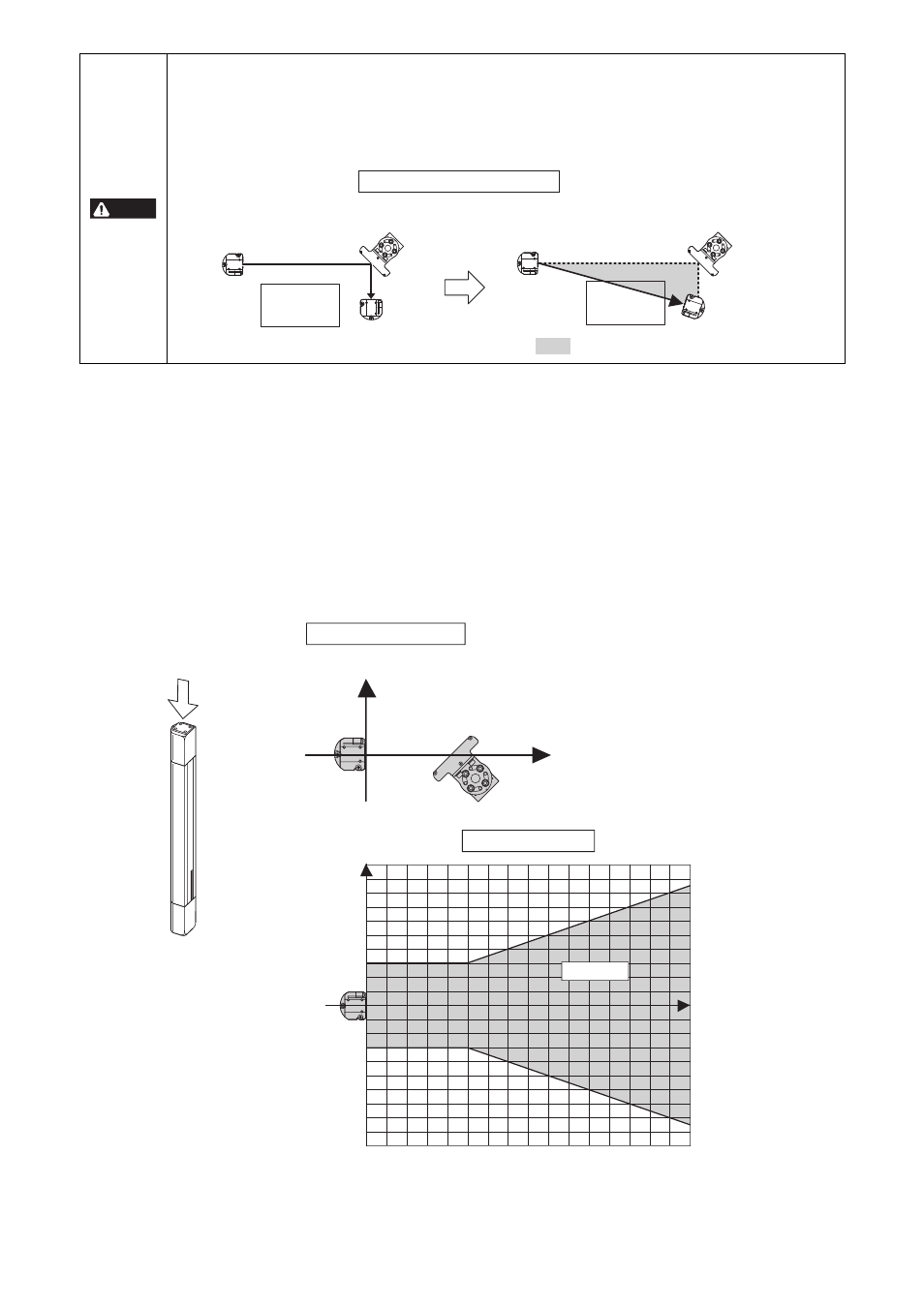
You must obey the following precautions relating to the installation positions of the SL-M Series and GL/SL Series.
• SL-M Series installation requirements based on the position of the GL/SL Series Transmitter or Receiver
Note that these requirements do not apply to just either the GL/SL Series Transmitter or Receiver but rather apply to both units.
When installing a GL/SL Series Transmitter at Position A on Graph 1
When a GL/SL Series Transmitter and one SL-M Series unit have been installed as indicated in Definition 1 in the following diagram, no
other SL-M Series units or GL/SL Series Receiver can be installed in Area B in Graph 1. In other words, only one SL-M Series unit can
be installed in Area B. (When installing two or more SL-M Series units, see “SL-M Series, GL/SL Series Transmitter or Receiver
installation requirements based on the position of the SL-M Series” for more information.)
When installing a GL/SL Series Receiver at Position A on Graph 1
When an GL/SL Series Receiver and one SL-M Series unit have been installed as indicated in Definition 1 in the following diagram, no
other SL-M Series units or GL/SL Series Transmitter can be installed in Area B in Graph 1. In other words, only one SL-M Series unit
can be installed in Area B. (When installing two or more SL-M Series units, see “SL-M Series, GL/SL Series Transmitter or Receiver
installation requirements based on the position of the SL-M Series” for more information.)
When using the SL-M Series to create a detection zone where the approach of human body or objects to a hazard can be
detected, a misalignment in the mounting angle of either the GL/SL Series or SL-M Series may cause the beam from the GL/SL
Series Transmitter to enter the GL/SL Series Receiver without being reflected by the mirror surfaces of all or some of the installed
SL-M Series. This is extremely dangerous, as the system can not offer complete protection against the expected hazard and may
not be able to detect people or objects as they approach the hazard at the position where they must be detected. To avoid this
danger, install the SL-M Series in accordance with the following warnings. Failure to follow these warnings may result in significant
harm to machine operators, including serious injury or death.
DANGER
Transmitter
Misaligned
mounting angle
:Hazardous zone allowing human approach
SL-M
Intended system installation
System installation where misaligned
installation angles result in a hazardous zone
allowing human approach
Hazard
Receiver
Hazard
Seen from above (example)
Top
Transmitter or
receiver
Distance X
Distance X
Transmitter or
Receiver
Distance Y
SL-M
SL-M
Distance Y
(mm)
0 0.5 1 1.5 2 2.5 3 3.5 4 4.5 5 5.5 6 6.5 7 7.5
8
(1.64 ft.) (4.92 ft.) (8.20 ft.) (11.48 ft.) (14.76 ft.) (18.04 ft.) (21.33 ft.) (24.61 ft.)
(3.28 ft.) (6.56 ft.) (9.84 ft.) (13.12 ft.) (16.40 ft.) (19.69 ft.) (22.97 ft.) (26.25 ft.)
Distance X (m)
Area B
Graph 1 (top view)
Definition 1 (top view)
A: Transmitter
or Receiver
installation
position
1000 ( 39.37")
900
(
35.43")
800
(
31.50")
700
(
27.56")
600
(
23.62")
500
(
19.68")
400
(
15.74")
300
( 11.81")
200
( 7.87")
100
( 3.94")
0
-100 ( -3.94")
-200 ( -7.87")
-300 ( -11.81")
-400 (
-15.74")
-500 (
-19.68")
-600 (
-23.62")
-700 (
-27.56")
-800 (
-31.50")
-900 (
-35.43")
-1000 ( -39.37")