KEYENCE AP-30 Series User Manual
Ap-30 series, Two-color digital display pressure sensor, Instruction manual
Brown
Black or white
Blue
12 to 24 VDC
0 V
Load
Two-color Digital Display
Pressure Sensor
AP-30 Series
Instruction Manual
SPECIFICATIONS
1. The zero-shift type sensor is suffixed with Z after the model name.
2. Z type only. 3. Not provided with Z type
■
ACCESSORIES
e
p
y
T
e
v
i
t
a
g
e
N
e
r
u
s
s
e
r
p
e
r
u
s
s
e
r
p
e
v
i
t
i
s
o
P
d
n
u
o
p
m
o
C
e
r
u
s
s
e
r
p
l
e
d
o
M
.
1
)
Z
(
1
3
-
P
A
)
Z
(
2
3
-
P
A
)
Z
(
3
3
-
P
A
)
Z
(
4
3
-
P
A
e
r
u
s
s
e
r
p
d
e
t
a
R
a
P
k
3
.
1
0
1
-
o
t
0
0
6
7
-
o
t
0
(
)
g
H
m
m
a
P
k
0
.
0
0
1
o
t
0
1
o
t
0
(
m
c
/
f
g
k
2
)
a
P
M
0
0
0
.
1
o
t
0
0
1
o
t
0
(
m
c
/
f
g
k
2
)
o
t
3
.
1
0
1
+
a
P
k
3
.
1
0
1
–
g
H
m
m
0
6
7
+
(
)
g
H
m
m
0
6
7
-
o
t
e
r
u
s
s
e
r
p
f
o
o
r
P
a
P
k
0
9
4
m
c
/
f
g
k
5
(
2
)
a
P
k
0
9
4
m
c
/
f
g
k
5
(
2
)
a
P
M
7
4
.
1
m
c
/
f
g
k
5
1
(
2
)
a
P
k
0
9
4
m
c
/
f
g
k
5
(
2
)
e
p
y
t
e
r
u
s
s
e
r
P
e
r
u
s
s
e
r
p
e
g
u
a
G
s
e
p
y
t
d
i
u
l
F
s
e
s
a
g
e
v
i
s
o
r
r
o
c
n
o
n
r
o
r
i
A
y
a
l
p
s
i
D
)
m
m
1
1
:
t
h
g
i
e
h
r
e
t
c
a
r
a
h
C
(
D
E
L
t
n
e
m
g
e
s
-
7
,
r
o
l
o
c
-
2
,
t
i
g
i
d
-
2
/
1
3
n
o
i
t
u
l
o
s
e
r
y
a
l
p
s
i
D
,
a
P
k
1
.
0
,
g
H
m
m
1
i
s
P
2
0
.
0
,
a
P
k
1
.
0
m
c
/
f
g
k
1
0
0
.
0
2
,
i
s
P
2
0
.
0
,
a
p
M
1
0
0
.
0
m
c
/
f
g
k
1
0
.
0
2
,
i
s
P
2
.
0
,
a
P
k
2
.
0
,
g
H
m
m
2
i
s
P
4
0
.
0
e
g
n
a
r
e
r
u
s
s
e
r
p
e
l
b
a
t
c
e
t
e
D
.
S
.
F
f
o
%
0
1
1
+
o
t
%
5
1
-
y
t
i
l
i
b
a
t
a
e
p
e
R
±
)
e
r
o
m
r
o
s
m
5
(
.
S
.
F
f
o
%
2
.
0
g
n
i
r
e
t
t
a
h
c
(
e
m
i
t
e
s
n
o
p
s
e
R
)
n
o
i
t
c
n
u
f
n
o
i
t
n
e
v
e
r
p
)
e
l
b
a
t
c
e
l
e
s
(
s
m
0
0
5
/
0
0
1
/
5
/
5
.
2
t
u
p
n
i
t
f
i
h
s
-
o
r
e
Z
.
2
,
)
e
t
a
t
s
-
d
il
o
s
,
t
c
a
t
n
o
c
(
t
u
p
n
i
e
g
a
t
l
o
v
-
n
o
N
e
r
o
m
r
o
s
m
0
2
:
e
m
i
t
t
u
p
n
I
t
u
p
t
u
o
l
o
r
t
n
o
C
l
a
u
d
i
s
e
R
,
)
.
x
a
m
V
0
4
(
.
x
a
m
A
m
0
0
1
:
r
o
t
c
e
ll
o
c
-
n
e
p
o
N
P
N
)
e
l
b
a
t
c
e
l
e
s
.
C
.
N
/
.
O
.
N
(
t
u
p
t
u
o
-
2
.
x
a
m
V
1
:
e
g
a
t
l
o
v
t
u
p
t
u
o
g
o
l
a
n
A
.
3
k
7
4
:
e
c
n
a
d
e
p
m
i
d
a
o
L
(
V
5
o
t
1
Ω
)
.
n
i
m
n
o
i
t
a
u
t
c
u
l
f
e
r
u
t
a
r
e
p
m
e
T
t
u
p
t
u
o
g
o
l
a
n
a
r
o
f
±
5
2
t
a
e
r
u
s
s
e
r
p
g
n
i
t
c
e
t
e
d
f
o
)
.
S
.
F
f
o
(
.
x
a
m
%
2
°
0
5
o
t
0
(
C
°
)
C
n
o
i
t
a
u
t
c
u
l
f
e
r
u
t
a
r
e
p
m
e
T
y
a
l
p
s
i
d
r
o
f
±
5
2
t
a
e
r
u
s
s
e
r
p
g
n
i
t
c
e
t
e
d
f
o
)
.
S
.
F
f
o
(
.
x
a
m
%
1
°
0
5
o
t
0
(
C
°
)
C
n
o
i
t
p
m
u
s
n
o
c
t
n
e
r
r
u
C
)
V
2
1
t
a
(
A
m
0
9
,
)
V
4
2
t
a
(
A
m
0
5
y
l
p
p
u
s
r
e
w
o
P
C
D
V
4
2
o
t
2
1
±
.
x
a
m
%
0
1
:
)
p
-
p
(
e
l
p
p
i
R
,
%
0
1
e
r
u
t
a
r
e
p
m
e
t
t
n
e
i
b
m
A
0
5
o
t
0
°
C
y
t
i
d
i
m
u
h
e
v
i
t
a
l
e
R
%
5
8
o
t
5
3
n
o
i
t
a
r
b
i
V
,
Y
,
X
n
i
e
d
u
t
il
p
m
a
e
l
b
u
o
d
m
m
5
.
1
,
z
H
5
5
o
t
0
1
y
l
e
v
i
t
c
e
p
s
e
r
s
r
u
o
h
2
,
s
n
o
i
t
c
e
r
i
d
Z
d
n
a
l
a
i
r
e
t
a
M
,
T
E
P
:
t
e
e
h
s
l
e
n
a
p
t
n
o
r
F
,
e
d
i
m
a
y
l
o
P
:
g
n
i
s
u
o
h
t
n
o
r
F
,
c
n
i
z
t
s
a
c
-
e
i
D
:
t
r
o
p
e
r
u
s
s
e
r
P
,
e
n
o
f
l
u
s
y
l
o
P
:
g
n
i
s
u
o
h
r
a
e
R
e
l
b
a
c
e
r
y
t
b
a
c
f
o
o
r
p
-
li
O
:
e
l
b
a
C
t
h
g
i
e
W
)
e
l
b
a
c
m
2
g
n
i
d
u
l
c
n
i
(
g
0
2
1
.
x
o
r
p
p
A
• Instruction manual: 1
• Hexagonal-socket
port stopper: 1
• Display unit
label sheet: 1
• Quick reference
sheet: 1
Mounting
bracket A: 1
Mounting
bracket B: 1
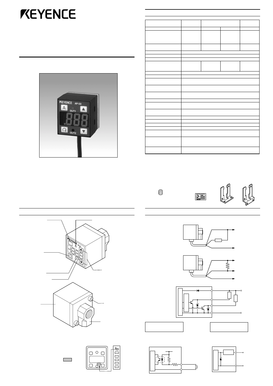
PART NAMES AND FUNCTIONS
AUTO key
In auto-tuning mode, use
this key to detect pres-
sure. In measurement
mode, press this key for 2
seconds or more to adjust
the zero-point.
SET key
Use this key to display or
change preset values.
Output indicator 2
(Green LED)
Display unit label
Output indicator 1
(Red LED)
UP/DOWN key
Use these keys to
set output modes,
or to change preset
values or units.
Housing
Hexagonal
socket bolt
A
■
Display unit label
The AP-30 series enables you to
select the display units for pressure.
Attach the included display unit label
for the desired units at the
position in the figure.
CONNECTIONS AND INPUT/OUTPUT CIRCUIT
■
Connections
• Drive current load
• Input to voltage input equipment
■
Input/output circuit
• Output circuit
Brown
Black or white
Blue
12 to 24 VDC
4.7 k
Ω
0 V
Voltage output
Brown
Black
Blue
12 to 24 VDC
0 V
White
(Control output 1)
(Control output 2)
Load
Load
Pressure sensor main circuit
Over current
protection circuit
AP-31Z/32Z/33Z/34Z
(Z type only)
Input circuit (Zero-shift input)
Zero-shift input resets the display to
“0” at the rising edge of the signal.
Blue
Pink
Pressure sensor
main circuit
12 to 24 VDC
3.3 k
Ω
11 k
Ω
AP-31/32/33/34
(Except for Z type)
Analog output circuit
Blue
Pink
Analog
output (+)
0 V
Protection
circuit
Pressure sensor
main circuit
Rear metal casing
(Die-cast zinc)