Adjustment, Dt s, Hc n i – KEYENCE AP-40P User Manual
Page 4: Ra b
4
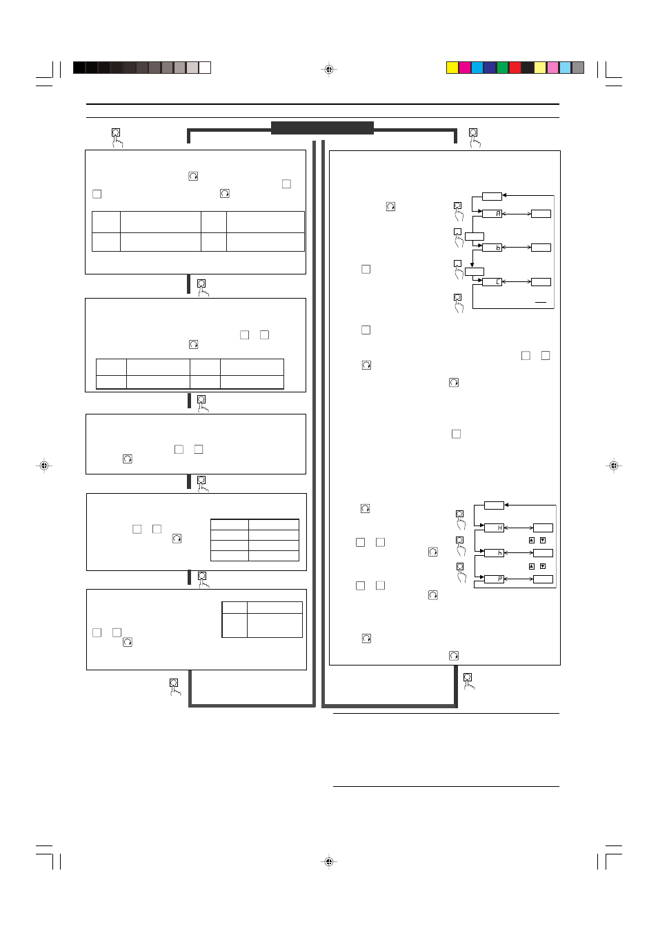
■ Unit Setting
Determine the desired units.
In measurement mode, press
for at least 3 seconds. “- - - -”
appears first, and then the current units are displayed. Use
▲
or
▼
to select the desired units. Pressing
completes the unit
setting procedure and enters operation mode selection.
■ Operation Mode
Determine the desired operation mode.
(
➮
Refer to “OPERATION MODE SELECTION” on page 3.)
The current operation mode is displayed. Use
▲
or
▼
to select
the operation mode. Pressing
completes the operation mode
setting procedure and enters N.O./N.C. selection.
■ N.O./N.C. Selection
Select N.O. (normally open) or N.C. (normally closed).
The current selection of “
no
” (normally open) or “
nc
” (normally
closed) is displayed. Use
▲
or
▼
to select the desired mode.
Pressing
completes the N.O./N.C. selection procedure and
enters the chattering prevention setting.
■ Chattering Prevention
Determine the desired response time.
The current response time is dis-
played. Use
▲
or
▼
to select the
response time. Pressing
com-
pletes the setting procedure and
enters the display color selection.
■ Display Color Selection
Determine the desired LED color for
numerical value display.
The current color is displayed. Use
▲
or
▼
to select the color.
Pressing
completes the setting
procedure and returns to the
measurement mode.
ADJUSTMENT
Measurement mode
Press the button
for 3 seconds or
more.
Press the button
once.
d
t
S
,
g
H
m
m
:
4
4
/
)
M
(
1
4
-
P
A
m
c
/
f
g
k
:
3
4
-
P
A
2
A
P
,
a
P
k
:
4
4
/
)
M
(
1
4
-
P
A
a
P
M
:
3
4
-
P
A
h
c
n
i
,
g
H
h
c
n
i
:
4
4
/
)
M
(
1
4
-
P
A
:
3
4
-
P
A
i
s
P
R
A
b
r
a
b
:
4
4
/
3
4
/
)
M
(
1
4
-
P
A
Press the button once.
▲
Press the button once.
5
.
2
s
m
5
.
2
5
s
m
5
0
0
1
s
m
0
0
1
0
0
5
s
m
0
0
5
Press the button once.
[
-
1
y
l
n
o
D
E
L
d
e
R
[
-
2
D
E
L
n
e
e
r
g
/
d
e
R
t
u
p
t
u
o
n
e
h
w
D
E
R
(
)
N
O
s
n
r
u
t
1
Press the button once.
■ Preset Value Input Mode
Determine the preset values.
●
Auto-tuning mode (F-1)
1. In measurement mode with the
current measured value dis-
played, press
. The AP-40
enters the preset value input
mode.
2. “A” and the current preset value
flash alternately.
3. Position the target at the desired
upper (lower) limit.
4. Press
A
to register the value.
The updated value is displayed
for 1 second.
5. “b” and the current preset value
flash alternately.
6. Position the target at the desired
lower (upper) limit.
7. Press
A
to register the value. The updated value is displayed for 1
second.
8. “C” and the calculated preset value C flash alternately. (You can
change the C value to any value between A and b using
▲
or
▼
.)
9. Press
to register the C value. The setting procedure is com-
pleted and the unit returns to measurement mode.
* To confirm the preset value, press
repeatedly.
• Example of auto-tuning mode setting: Confirmation of work
piece pick-up.
Set the upper limit (A) to the position where the work piece is taken.
Set the lower limit (b) to the position where the nozzle becomes open
after releasing the work piece. Press
A
to register the upper and
lower limit values. The C value is automatically set to the midpoint
between the upper and lower limit values.
■ Hysteresis Mode (F-2), 2-independent Output
Mode (F-3), Window Mode (F-4)
1. In measurement mode with the
current measured value displayed,
press
. The AP-40 enters the
preset value input mode.
2. “H”
1.
and the current preset value
flash alternately.
3. Use
▲
or
▼
to change the value
to the desired value. Press
to
register the updated H value.
4. “h”
2.
and the current preset value
flash alternately.
5. Use
▲
or
▼
to change the value
to the desired value. Press
to
register the updated h value.
6. “P”
3.
and the shift value of the
zero-shift adjustment flash
alternately.
8. Press
to complete the setting procedure and return to measure-
ment mode.
* To confirm the preset value, press
repeatedly.
❋ ❋ ❋ ❋
❋ ❋ ❋ ❋
❋ ❋ ❋ ❋
❋ ❋ ❋ ❋
❋ ❋ ❋ ❋
❋ ❋ ❋ ❋
• • •
• • •
• • •
• • •
A
A
(Measurement mode)
Current value
Flashes
alternately
Flashes
alternately
Flashes
alternately
Current upper
(lower) limit
value A
Current upper
(lower) limit
value b
The set value
C displays.
(C=
A + b
2
)
The updated value displays for 1 sec.
The updated value displays for 1 sec.
❋ ❋ ❋ ❋
❋ ❋ ❋ ❋
❋ ❋ ❋ ❋
• • •
• • •
1.
2.
3.
(Measurement mode)
Flashes
alternately
Current value
Flashes
alternately
Set the desired value
using
or
❋ ❋ ❋ ❋
Flashes
alternately
Set the desired value
using
or
• • •
[Example: In hysteresis mode]
1. “A” appears in the 2-independent
output mode.
2. “b” appears in the 2-independent
output mode.
“L” appears in the window mode.
3. Shown with Z type only.
* The setting is saved
in the EEPROM.
▲
▲
▲
▲
▲▲
▲
* When the units are changed, the preset values are automatically
converted to appropriate values for the updated units.
Press the button once.
* The setting is saved
in the EEPROM.
Press the button once.
1
-
F
e
d
o
m
g
n
i
n
u
t
-
o
t
u
A
3
-
F
t
n
e
d
n
e
p
e
d
n
i
-
2
e
d
o
m
t
u
p
t
u
o
2
-
F
e
d
o
m
s
i
s
e
r
e
t
s
y
H
4
-
F
e
d
o
m
w
o
d
n
i
W
Note 1: When the operation mode is changed, check the preset values
in the preset value input mode.
Note 2: Perform the zero-shift adjustment periodically.
Note 3: The initial output voltage may fluctuate by
±
1.0% immediately
after the power is turned on. To measure minute differences in
pressure, let the sensor warm up for approximately 15 to 30 minutes.
Note 4: The amount of zero shift ("P") is displayed without multiplica-
tion even in the zero-shift focus mode.