Mounting, Connections and input/output circuit, Basic operation – KEYENCE AP-40A Series User Manual
Page 2: Attaching a spare connector, Safety precautions
2
Orange
Brown
Blue
Gray
1
2
3
4
3. Insert the cables into the proper holes as deep as possible. Then,
press the connector cover into the body with pliers.
Reference:
Note 1: Do not allow the cable to protrude from the other end of the
connector cover.
Note 2: Ensure that the cables are inserted as far as they will go. If
the inserted length is insufficient, the press-fitting fails.
CAUTION
MOUNTING
■
AP-40A/40RA/40ZA
As shown in the figure with "Amplifier accessories" on page 1, attach
the mounting bracket to the amplifier with hexagonal socket bolts.
The mounting bracket can be attached laterally according to the
location.
To avoid breakage, limit the tightening torque
for the hexagonal socket bolt to 0.3 N•m.
■
AP-41(M)/43/44
Limit the tightening torque for the screw hole of
the sensor head to 0.3 N•m.
■
AP-48
• Limit the tightening torque on the screw to 5 N•m.
• The AP-48 is only compatible with the AP-40RA.
• If one of the pressure ports is to be left open, ensure that foreign
objects can not enter the port.
• To avoid deformation or damage during mounting, do not apply
force to the sensor body.
■
Zero-point adjustment
At normal atmospheric pressure (1 atm.), press
A
for at least 2
seconds in measurement mode. The display changes to “----”, then to
“
0
”. The zero adjustment function can be used when the pressure is
within
±
5% of F.S.
CAUTION
BASIC OPERATION
Basic operation (See also "ADJUSTMENT" on page 4.)
●
Checking the suction condition
1. Select F-3 (2-independent mode) and return to the measurement
mode.
➮
Refer to the setting in "Operation Mode" on the left-hand side of page 4.
2. Enter the target pressure value (A) and return to the measurement
mode. (You can specify another target pressure value (b).)
➮
Refer to the setting in "Preset Value Input Mode" on the right-hand side of
page 4.
3. Start detection.
●
Base pressure control
1. Select F-4 (Window mode) and return to the measurement mode.
➮
Refer to the setting in "Operation Mode" on the left-hand side of page 4.
2. Enter the upper (H) and lower (L) limit values of the allowable
pressure and return to the measurement mode.
➮
Refer to the setting in "Preset Value Input Mode" on the right-hand side of
page 4.
3. Start detection.
ATTACHING A SPARE CONNECTOR
Use the spare connector to change the length of the sensor head
cable. Cables as long as 10 m can be used.
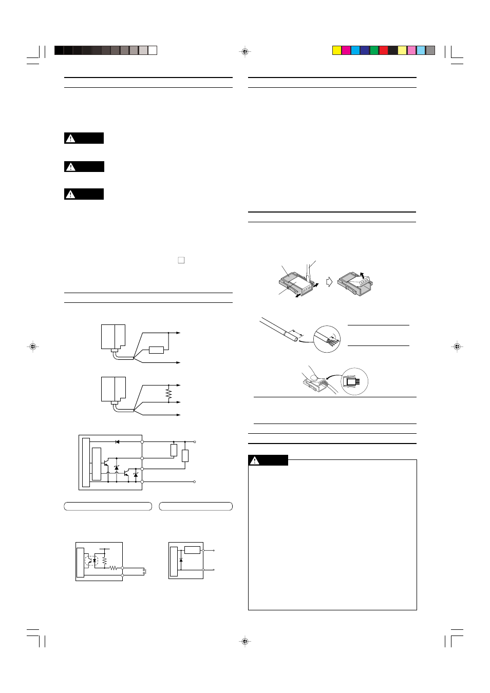
1. If the connector cover is fitted into the connector body, open the
cover.
2. Cut a cable to the appropriate length and strip off the sheath for
approximately 25 mm from the end.
Connector body
Slotted screwdriver
Connector cover
1. Widen the gap.
2. Lift the end of the cover.
Approx.
25 mm
SAFETY PRECAUTIONS
Be sure to follow the instructions below to avoid malfunctions.
■
Connection
• When using a commercially available switching regulator, be sure
to ground the frame ground terminals.
• Isolate the sensor’s wiring from power lines or high-voltage lines;
otherwise, the sensor may malfunction due to noise interference.
• The amplifier becomes hot or breaks down due to improper wiring.
• The press-fitting is available only once for each sensor head
connector.
■
Notice about CE marking
• Attach the ferrite core (OP-87505) if you extend a sensor head
cable/ amplifier power cable to 3 m or more to use.
(Attachment position: within 100 mm from the amplifier unit of a
power cable, Number of turns: 2)
■
Other
• Do not use the AP-40A Series for the detection of corrosive gases
or liquid.
• Do not insert any objects, such as wires, from the pressure port.
The pressure-sensing element may break, resulting in malfunc-
tions.
• Do not press the front panel keys with a pointed object.
• The AP-40A Series does not have an explosion-proof structure.
Do not use it for the detection of flammable gases.
CAUTION
Note: It is not necessary
to remove the sheath of
the core wire.
Approx.
25 mm
CONNECTIONS AND INPUT/OUTPUT CIRCUIT
■
Connections
• Drive current load
• Input to voltage input equipment
■
Input/output circuit
• Output circuit
Brown
Black or white
Blue
12 to 24 VDC
0 V
Load
Brown
Black or white
Blue
12 to 24 VDC
4.7 k
Ω
0 V
Voltage output
Brown
Black
Blue
12 to 24 VDC
0 V
White
(Control output 1)
(Control output 2)
Load
Load
Pressure sensor main circuit
Over current
protection circuit
Blue
Pink
Pressure sensor
main circuit
12 to 24 VDC
3.3 k
Ω
11 k
Ω
Blue
Pink
Analog
output (+)
0 V
Protection
circuit
Pressure sensor
main circuit
• Input circuit (Zero-shift input)
Zero-shift input resets the display
to “0” at the rising edge of the
signal.
• Analog output circuit
AP-40RA/40ZA
(RA/ZA type only)
AP-40A
(40A type only)
CAUTION