Sensor configuration – KEYENCE AP-C40(P) Series User Manual
Page 3
3
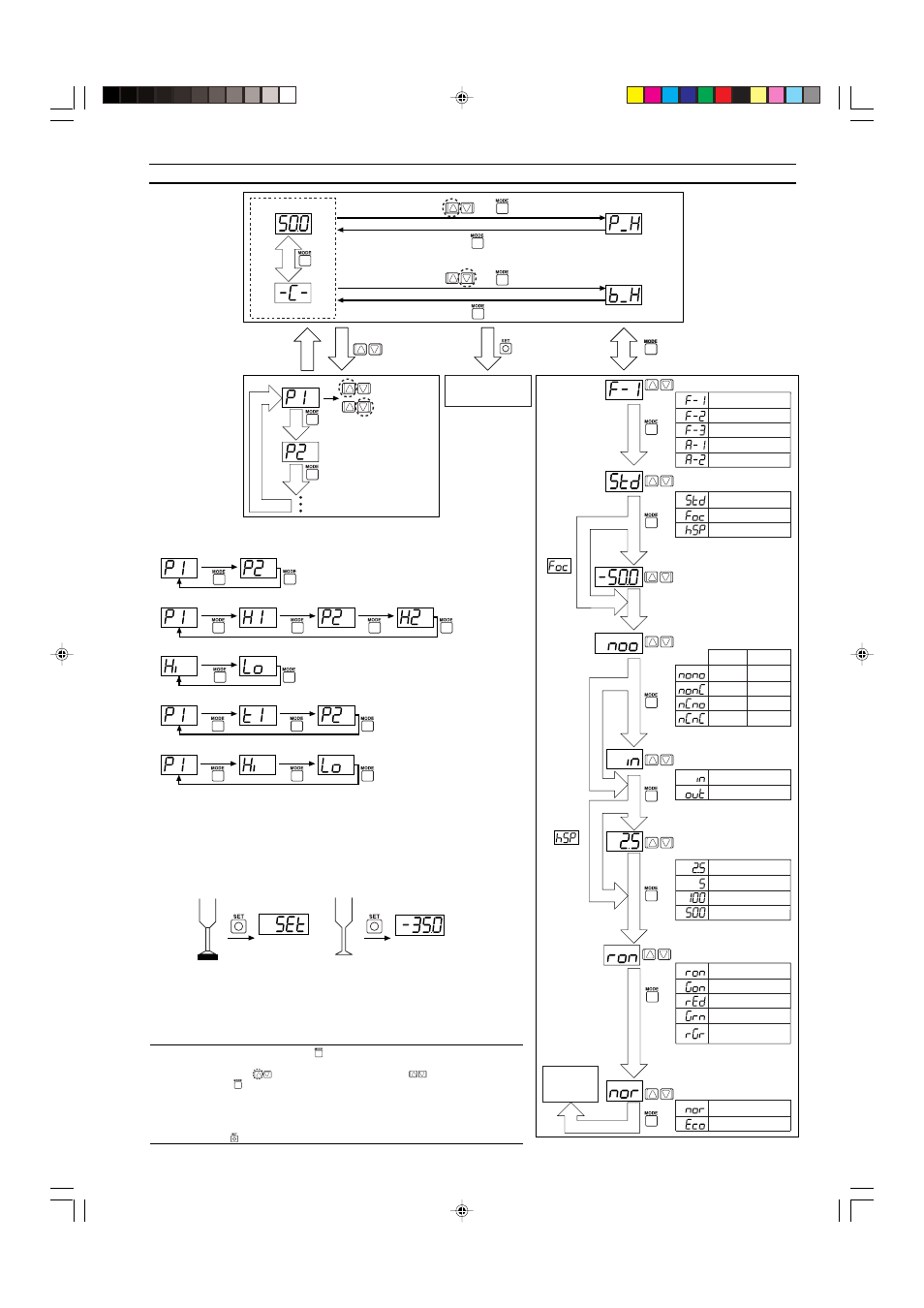
Detection mode
Operating mode
Standard
Focus mode
High-speed
Zero shift input
Analog output
N.O./N.C.
2.5
msec
5
msec
100
msec
500
msec
General-purpose mode
Variable hysteresis mode
Window mode
Application mode 1
Application mode 2
Analog/zero shift
Standard
Eco mode
Power-save
Chatter prevention
Sets response time.
* F-1 and F-2 mode only
Values that fall between the P1 and P2
settings will be displayed in green,
while values outside that range will be
displayed in red.
When
A-1/A-2 is
selected
during
fixed mode
operation
When
operating
mode is
• Two-point tuning
• Active tuning
* High-speed mode provides a 1-ms
high-speed response.
Current value
Reference value
Hold value
Increase the
setting.
Decrease the
setting.
For other
than
Focus center pressure
After 4 sec
of no key
operation.
Reference value*
Press for 3 sec or more.
+
+
■
Toggling the
display
■
Manual configuration
Settings are
manually
configured. The
display changes
for each mode.
* Toggling the
display of
settings (see the
diagram below).
* Manual configuration
only during F-3/A-2
mode operation.
Current value
Peak hold
Bottom hold
* The reference value is
the pressure value when
zero shift input is
received and is replaced
only when zero shift
input is selected.
■
Mode
configuration
* See the Focus Mode section
of Part 10 for the center
pressures that can be
selected.
N.O.
N.O.
N.C.
N.C.
N.O.
N.C.
N.C.
N.O.
Control
output 1
Control
output 2
• N.O.
= normal open.
• N.C.
= normal close.
Display color (7-segment)
ON: Red, OFF: Green
ON: Green, OFF: Red
Normally red
Normally green
Within set value: Green
Outside set value: Red
(
)
9. Sensor Configuration
■
Toggling the display of settings
●
General-purpose mode/F1
●
Variable hysteresis mode/F-2
●
Window mode/F-3
●
Application mode 1/A-1
●
Application mode 2/A-2
■
Two-point tuning (F-1/F-2)
The sensor is made to detect the pressures when the target object is
present and then absent for confirmation of target suction pick-up, and
the intermediate value is used.
Control output 1 configuration: When P1 (H1) is selected on the settings
display.
Control output 2 configuration: When P2 (H2) is selected on the settings
display.
Flashes
for 3 sec.
Setting
Target object
present
Target object
absent
■
Active tuning (A-1)
See Section 11.
Note:• Press and hold the MODE button (
) for at least 3 seconds to return to the current
value/reference value/hold value display from each of the mode setting screens.
• Press the left side
on the manual adjustment button (
) while holding down the
mode button (
) to return to the previous display.
• The current value will be displayed based on the ambient pressure conditions prevalent
at that time without regard to zero shift input when the P2 setting display is selected for
A-1 mode or when the HI and Lo setting displays are selected for A-2 mode.
• The sensor must be configured manually when operating in the F-3/A-2 modes. The
SET button (
) will not function.