Connection method and diagrams, Precautions for safe use, Detection mode operation – KEYENCE AP-C30WP User Manual
Page 2: Ap-ao1 panel mounting bracket, Analog output circuit, Zero shift input circuit, Connections input/output circuit
2
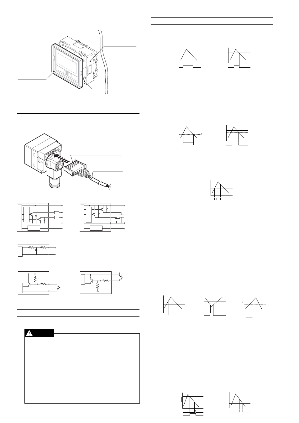
AP-AO1 Panel mounting bracket
SE
T
AP
-C
33
MO
DE
MP
a
SE
T
AP
-C
40
MO
DE
MP
a
Panel mounting ring
Panel-mounted sample
Panel-mounted sample
Front protective
cover
Panel-mounted sample
5. Connection Method and Diagrams
Insert the included connector-tipped cable into the sensor’s connector.
Position the connector so that the side of the connector where the metallic
contacts are visible is facing up.
Connector cable
Side where the metallic
contacts are visible faces up.
Input/output circuit
Input/output circuit
(AP-C30W/C31W/C33W)
(AP-C30WP/C31WP/C33WP)
12 to 24 VDC
5 to 40 VDC
5 to 40 VDC
0V
Main circuit
Ov
ercurrent
protection circuit
Load
Load
Input/output
circuit
Analog output/
zero shift input: switchable
Brown
Blue
Black
White
Pink
12 to 24 VDC
0V
Main circuit
Ov
ercurrent
protection circuit
Input/output
circuit
Analog output/
zero shift input: switchable
Brown
Blue
Black
White
Pink
Load
Load
Analog output circuit
Analog
output (1 to 5 V)
0 V
Main
circuit
Blue
Pink
Zero shift input circuit
Zero shift input circuit
(AP-C30W/C31W/C33W)
(AP-C30WP/C31WP/C33WP)
(Short-circuit current 5 mA max.)
Main
circuit
Blue
Pink
12 to 24 VDC
Main
circuit
Pink
(Short-circuit current 5 mA max.)
Brown
Use non-contact input device such as open-collector.
6. Precautions for Safe Use
Follow these guidelines. Failure to do so may result in product damage.
CAUTION
■
Connections
Input/output circuit
●
Always ground the frame ground terminal when using an off-the-shelf
switching regulator.
●
Use separate conduits for power line and high voltage lines, since use
of a common conduit may result in device malfunction.
●
Improper wiring may result in the device becoming excessively hot or
in device damage.
■
Other
●
Do not use this sensor with corrosive gasses or liquids.
●
Do not insert objects such as wire into the pressure insertion area.
Doing so may result in the device failing to operate properly due to
damage to the pressure-sensitive elements.
●
Do not use sharp-tipped objects to press the setting keys.
7. Detection Mode Operation
■
General-purpose mode (F-1)
This mode allows the user to configure 2 detection points.
Control output 1: Turns ON when pressure exceeds setting P1.
Control output 2: Turns ON when pressure exceeds setting P2.
P1
0
Output 1
OFF
ON
OFF
P2
0
OFF
ON
OFF
Output 2
*Hysteresis is a standard 0.5% of F.S. when operating in general-pur-
pose mode and application modes 1 and 2. During focus mode op-
eration, it is 0.2% of F.S.
■
Variable hysteresis mode (F-2)
Two detection points may be user-configured, and hysteresis for both
may also be set.
Control output 1: Turns ON when pressure exceeds setting P1. Turns OFF
when pressure drops the selected hysteresis amount
below P1.
Control output 2: Turns ON when pressure exceeds setting P2. Turns OFF
when pressure drops the selected hysteresis amount
below P2.
P1
H1
Output 1
OFF
ON
OFF
0
P2
OFF
ON
OFF
H2
0
Output 2
■
Window mode (F-3)
The user may select a pair of upper (Hi) and lower (Lo) thresholds, and
the sensor turns OFF when the pressure falls outside of the resulting
range.
*Control output 1 is a standard 0.5% of F.S. During focus mode opera-
tion, it has a hysteresis of 0.2% of F.S., and control output 2 has a
hysteresis of 0.
Hi
Lo
Output1/Output2
OFF
ON
ON
OFF
OFF
0
■
Application mode 1 (A-1)
This detection mode is optimum for use in suction detection applica-
tions.
Recommended sensor heads: AP-C30W/C30WP/C31W/C31WP
Control output 1: Suction pressure detection.
Turns ON when pressure exceeds setting P1.
Control output 2: Detection and confirmation of vacuum burst pressure
detection (or vacuum ultimate pressure).
Turns ON when the pressure falls below setting P2.
*Cannot be used to detect vacuum burst pressure with
the AP-C31W/C31WP when operating in focus mode.
Standard mode operation only.
Zero shift:
The zero point is shifted immediately after the zero
shift timer is set following the activation of zero shift
input.
P1: Pressure setting for control output 1.
T1: Zero shift timer setting (ms) < Variable between 0 and 1,999 ms>
P2: Pressure setting for control output 2.
*P2 is unrelated to zero shift and is always based on the current ambi-
ent pressure.
P1
Output 1
OFF
ON
OFF
0
0
Output 2
OFF
ON
OFF
P2
0
0
Shift
Zero shift input
T1
■
Application mode 2 (A-2)
This mode is optimum for use in leak test applications.
Recommended sensor head: AP-C33W/C33WP
Control output 1: Leak pressure detection.
Turns ON when pressure falls below setting P1.
*Output only when receiving zero shift input.
Control output 2: Window comparator output for detection of fill pressure.
Turns OFF when pressure falls outside the range deter-
mined by upper (Hi) and lower (Lo) thresholds.
*Fill pressure values are displayed with the center pres-
sure as 0 during focus mode operation.
P1: Pressure setting for control output 1.
Hi: Upper threshold setting for control output 2.
Lo: Lower threshold setting for control output 2.
*The Hi and Lo values are unrelated to zero shift and are always based
on the current ambient pressure.
P1
Output1
Zero shift input
OFF
ON
OFF
ON
0
Hi
Lo
Output 2
OFF
ON
OFF
OFF
ON