Connecting to the controller, Console connector, Panel lock – KEYENCE CA-MP120T User Manual
Page 2: Installation procedure, Connecting the 24 vdc power source, Adjustment procedure
2
The only consoles that can be connected are the OP-84231 or the OP-84236. Otherwise, do
not make any other connections because it may be the cause of erroneous operation.
When attempting to prevent water from entering the front surface, tighten the console cap
with 0.8 Nm.
1. The PANEL LOCK will activate when the automatic adjustment indicator lights up or when
the PANEL LOCK button is held down.
2. The PANEL LOCK will be deactivated when the PANEL LOCK button is pressed.
1. Insert the CA-MP120T into the panel.
2. Using the 6 installation hooks on the top and bottom of the CA-MP120T, tighten the
screws of the mounting bracket using a Phyllis-head screwdriver.
The CA-MP120T can not only be installed to the panel bracket, it can be installed to the
monitor stand for CA Series LCD monitor use (optional). For details inquire to your nearest
KEYENCE office.
If your monitor needs adjustment due to ambient light, the installation angle, or the
characteristics of the connected device, follow the procedure below.
1. Press the
button on the rear of the monitor. The setting menu is displayed.
2. Press the
button to move the cursor onto the item to change the setting.
3. Press the
button to change the setting of the item.
4. Press the
button to change the value/setting.
5. Press the
button to return to the status of step 1.
6. When you complete the adjustment, press the
button to exit the setting menu.
Connecting to the controller
Image signal
input
Connect by using an RGB monitor cable OP-66842 (3 m), an OP-87055
(10 m), or a commercially available analog RGB cable.
Touch panel
signal input
When using a D-sub9Pin connector on the controller side:
connect using a touch panel RS-232C cable OP-87258 (3 m), or
OP-87259 (10 m).
When using a modular connector on the controller side:
connect using a touch panel modular RS-232C cable OP-87264 (3 m),
or OP-87265 (10 m).
Console signal
output
Connect the modular connector for console use with the console
connector cable OP-87260 (3 m) or the OP-87261 (10 m).
Console connector
PANEL LOCK
Installation Procedure
• Tightening the mounting bracket with excessive force may deform
the casing. The proper tightening torque for achieving the drip-proof
feature is 0.3 Nm. However, note that a drip-proof effect may not be
obtained depending on the strength or shape of the panel.
• When installing the CA-MP120T, make sure to leave a minimum
clearance of 20 mm around the product.
Connecting the 24 VDC Power Source
• Use electrical wiring AWG14 to AWG22.
• Make sure to connect the frame ground terminal for the 24 VDC
power source to a type D ground.
• The sizes of solderless connectors are shown below. Use connectors
that fit M3 screws.
• Tighten the screws with a torque of 0.5 to 0.75 Nm.
When using a controller’s modular connector for touch
panel signal use, it is necessary to switch the port
function on the controller side. For details refer to the
controller manual.
Reference
Panel (Panel thickness): 1.0 to 4.0 mm
2
1
Mounting hook
Screw
Mounting bracket
Mounting bracket
Phillips screwdriver
NOTICE
NOTICE
5.8 mm or
smaller
Circular connector
5.8 mm or smaller
Y connector
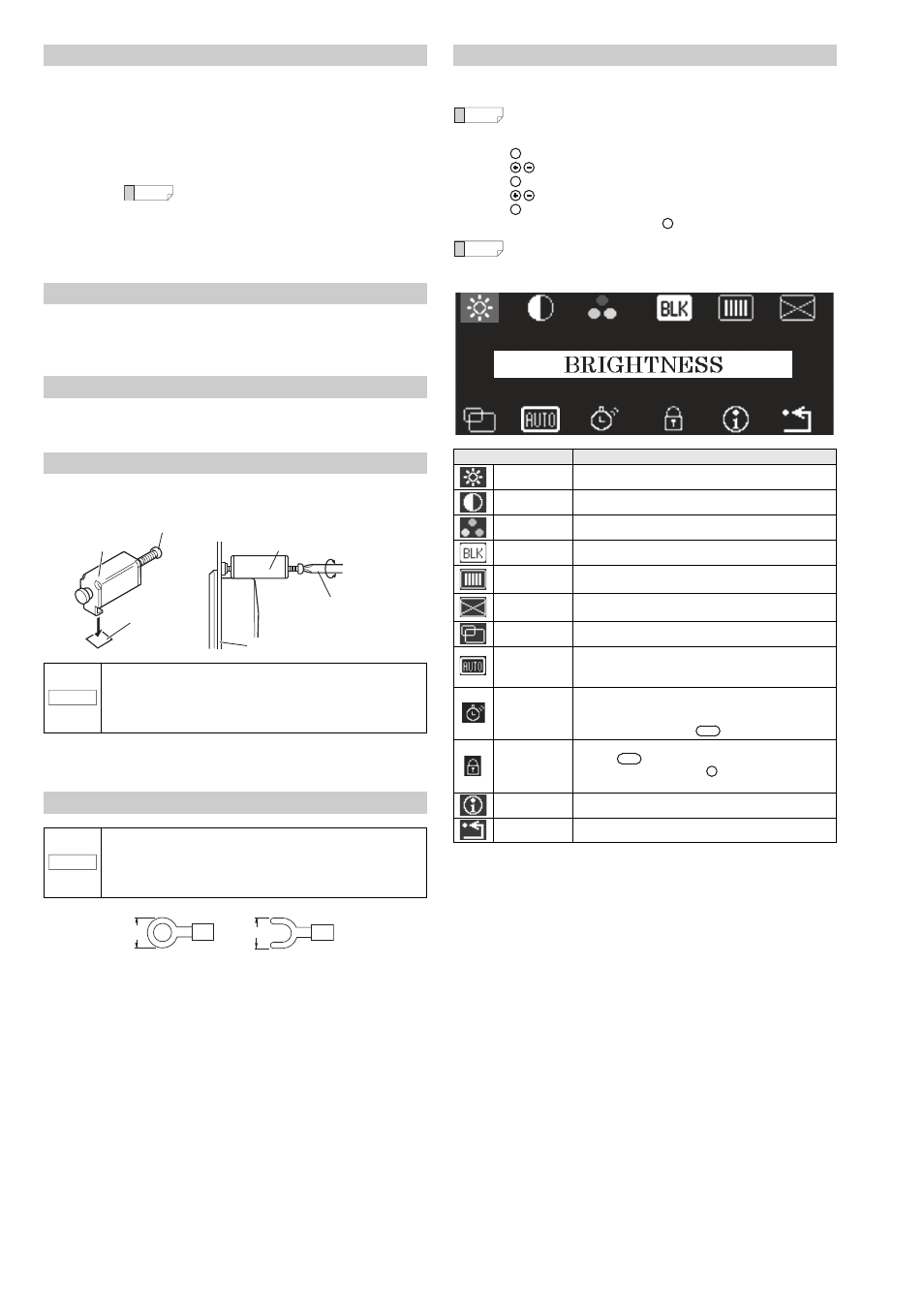
Adjustment Procedure
When no video signal is input, a blue screen (with message "NO SYNC
SIGNAL" for the first five minutes) is displayed instead of the setting menu.
Auto-escape function
If no button is pressed for about 10 seconds, the setting menu display is
turned off. When this occurs, the change(s) made so far will be saved.
Item
Setting
BRIGHTNESS
Adjusts the brightness of the backlight of the LCD panel.
CONTRAST
Adjusts the contrast of the image.
COLOR MODE
Adjusts the color tone of RGB individually.
BLACK LEVEL
Adjusts the black level.
CLOCK
Adjusts the horizontal size of the screen by adjusting the
clock.
FOCUS
Reduces blurred characters and images by adjusting the
focus.
POSITION
Adjusts the horizontal/vertical position of the screen.
*1
AUTO
ADJUSTMENT
The input image signal is adjusted automatically to the most
appropriate setting.
Adjustment object: POSITION/CLOCK/FOCUS
POWER
SAVING
The screen is set when the screen automatically lights up or
when the PANEL LOCK is set. It is deactivated when the
touch panel is touched, or by console operation. The PANEL
LOCK is deactivated by the
button.
BUTTON LOCK
All button operations are deactivated.
Also the
button operation is deactivated.
The lock is released when the
button is pressed for 3
seconds or more.
INFORMATION
Displays the device setting information, etc.
RECALL
Resets the settings to the factory default (initial) settings.
Reference
MENU
MENU
MENU
EXIT
Reference
PANEL LOCK
PANEL LOCK
MENU