Using mounting bracket f, Connecting the sensor head connection cable, Installing the air tube (gt2-pa12k/pa12) – KEYENCE GT2-PA12K/PA12 User Manual
Page 2: Compatible air tubes, How to attach/detach the air tube, Supplying air, Notice
2
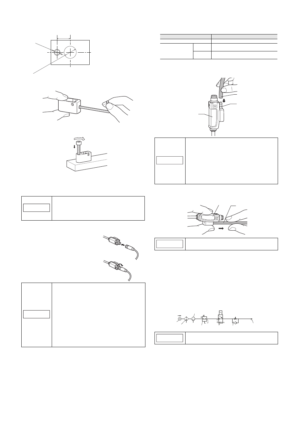
Using mounting bracket F
1
Refer to the illustration below, and cut the jig to create a sensor head
mounting hole.
2
Loosen the screw on the side of mounting bracket F using the
supplied hexagonal wrench.
3
Align mounting bracket F with the hole made in step 1 and secure it
using the supplied hexagonal wrench.
4
Insert the sensor head, and tighten the screw loosened in step 2
using the supplied hexagonal wrench to secure. The recommended
tightening torque is 0.6 to 0.8 N•m. Make sure that the dust boot does
not obstruct the metal plating that mounting bracket F is attached to.
Connecting the sensor head connection cable
1
Insert the sensor head connection cable
into the cable connector on the relay con-
nector cable.
2
Secure the connector with the sensor
head connecting cable screw.
Installing the air tube (GT2-PA12K/PA12)
Compatible air tubes
Use a tube with the following specifications.
How to attach/detach the air tube
• Attaching the air tube
Insert the air tube into the air supply hole on the relay amplifier.
• Detaching the air tube
To detach the air tube, pull the air tube in the direction of the arrow, as
indicated in the figure below.
Supplying air
• Refer to the diagram below to create a pneumatic circuit.
• Use an air filter, mist separator, etc. to provide clean dry air. Empty the
drainage from the filter regularly, before it exceeds the specified line.
• Make sure that the air pressure of the supplied air is constant and in the
range of 0.24 to 0.26 MPa. Use a precision regulator to control the air
pressure. If the air pressure is below 0.24 MPa, the spindle may not
extend fully.
• When supplying air (with the spindle extended), up to 3L/min of air will be
emitted from the tip of the dust seal.
• The measuring ability of the device changes according to the air pressure
of the air supply. Refer to "Specifications" for details.
NOTICE
• When loosening the screw with the hexagonal
wrench, insert the long end of the hexagonal
wrench into the hex screw and rotate the small end
with your hand.
• Do not forcibly tighten the hex screw.
NOTICE
• When connecting the connector, be sure to insert it
straight, and tighten it securely. (Recommended
tightening torque: 0.4 to 0.5 N•m
*
)
If the connection is not tight enough, the connector
may be loosened by vibration or other causes,
leading to a connection failure.
(* After tightening it strongly by hand, use pliers or
other tools to rotate it about 30° for further
tightening.)
• When the head is attached to a moving part, and the
cable will be repeatedly bent, ensure that the cable
between the sensor head and relay connector does
not bend. Instead, bend the sensor head cable
connecting the relay connector and the amplifier.
8.5
8
+0
.20
0
+0
.00
5
M4 x 0
.7
Make sure that the metal plating
mounting bracket F attaches to is at
least 5 mm thick.
Item
Description
Recommended tubing material
Urethane
Tubing size
Outer
diameter
4 mm
Inner
diameter
2.5 mm
NOTICE
• For best results, cut the end of the tube at a right
angle, ensure that the outer perimeter is not
damaged, and that it still maintains a circular cross
section.
• If the tube is not properly inserted, air leakage may
result.
• After attaching, pull on the tube to make sure it is
secure.
• Use a urethane tube. Make sure it also has a
bending radius of at least 50 mm.
NOTICE
Before detaching the tube, be sure to stop any air
flow.
NOTICE
If the air supply pressure exceeds 0.5 MPa, the sensor
head may become damaged.
Air tube
Air supply hole
Relay connector
Relay connector
Air tube
Mist separator
Air filter
Pressure
source
AIR
Solenoid valve
Precision regulator
Air supply part
GT2-PA12K/PA12
Speed controller