KEYENCE GT2-H12xxF User Manual
Gt2-h12f, Instruction manual, High-precision digital contact sensor
High-precision Digital Contact Sensor
GT2-H12F
Instruction Manual
Read this instruction manual carefully prior to operating this product. For
connection, settings and precautions on use, make sure to read the GT2 Series
instruction manual included with the amplifier.
For details of each function, refer to the GT2 Series User’s Manual.
You can download the User’s Manual from KEYENCE homepage (http://
www.keyence.co.jp).
Symbols
This instruction manual uses the following symbols that alert you to important
messages. Be sure to read these messages carefully.
Checking the Package
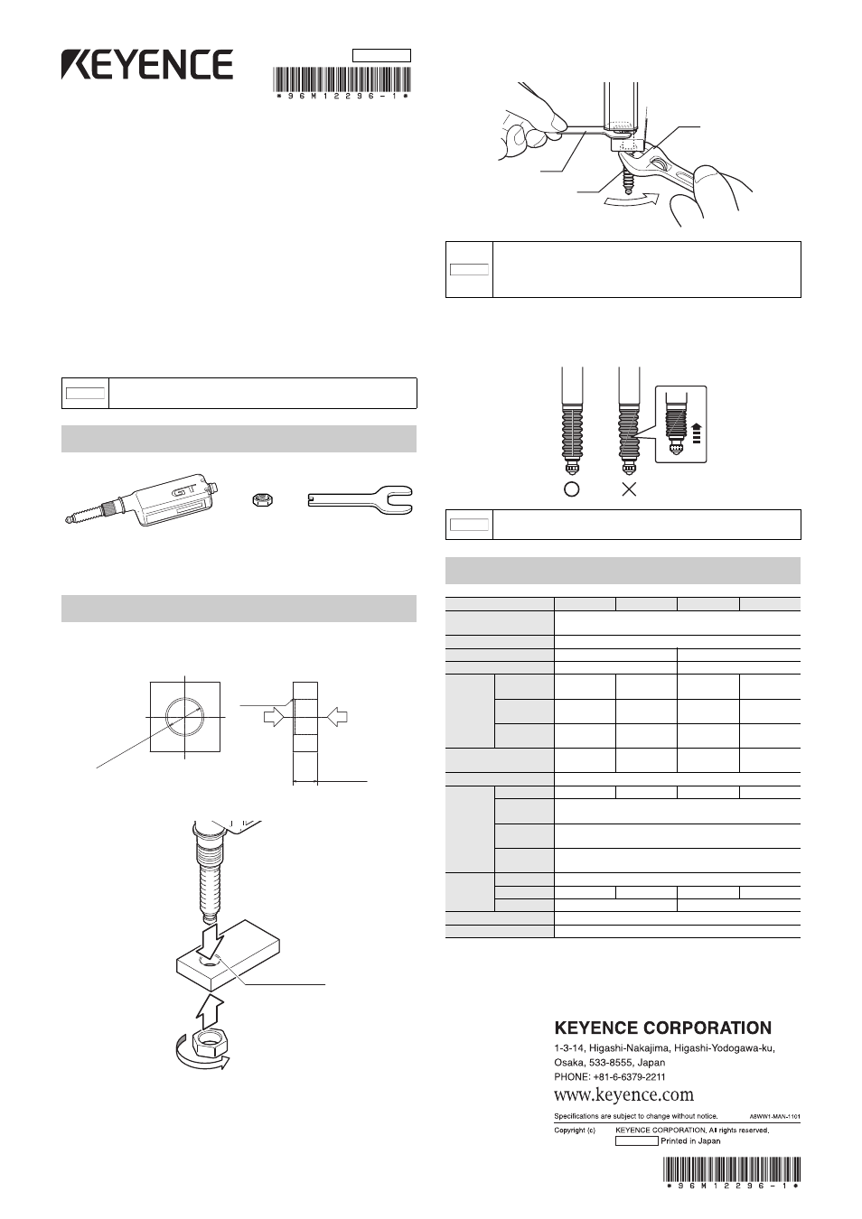
Mounting the Sensor Head
When mounting to the jig, make a round hole on the jig beforehand.
1
Work the sensor head mounting part as below.
2
Insert the sensor head to the hole worked in step 1.
3
Fixing the sensor head with the included spanner, tighten the nut with
a wrench or similar tool.
4
Rotate the dust boot for adjustment so that the side line of dust boot
becomes straight.
Check with the spindle pushed in.
Specifications
*1 Values at surrounding temperature of 20°C
*2 Typical values around measurement center values. Note that the measuring
force fluctuates according to the mounting conditions of dust boot.
*3 The contact is available as a separately sold item.
NOTICE
Failure to follow instructions may lead not only to the product
damage but to damages to other properties.
Sensor head × 1
Precautions for handling × 1
Instruction Manual (This manual) × 1
Nut × 1
Key spanner Ч 1
0.5Ч45°
Chamfer
Nut mounting side
5.5 to 11
Sensor head
insertion side
10
+0
.1
+0
.00
5
Chamfered side
Sensor head
Nut
NOTICE
•
Never apply tightening torque over 10 N•m (The
recommended tightening torque is 5 to 7 N•m).
•
Care must be taken not to damage the dust boot when
tightening.
NOTICE
If the dust boot is not straight, it will be easily damaged when
the spindle is moved.
Model
GT2-H12KF
GT2-H12KLF
GT2-H12F
GT2-H12LF
Detection method
Quartz glass scale C-MOS image sensor projection method
Absolute (without value skip) type
Measure range
12 mm
Resolution
0.1
m
0.5
m
Indication accuracy
*1
1
m(p-p)
2
m(p-p)
Measuring
force
*2
Mounted
downward
1.0 N
0.4 N
1.0 N
0.4 N
Mounted
sideways
0.9 N
0.3 N
0.9 N
0.3 N
Mounted
upward
0.8 N
0.2 N
0.8 N
0.2 N
Mechanical
responsiveness
*1
10 Hz
4 Hz
10 Hz
4 Hz
Operation status indicator
2-color LED (red, green)
Environment
al resistance
Protection code
IP67
–
IP67
–
Surrounding
air temperature
-10°C to +55°C (No freezing)
Surrounding
air humidity
35 to 85%RH (No condensation)
Vibration
resistance
10 to 55 Hz, double amplitude 1.5 mm in X, Y and Z directions,
2 hours respectively
Material
Main unit
Main unit case: Zinc die-cast, Indicator: Poly Arylate (PAR)
Dust boot
NBR
–
NBR
–
Contact
*3
SUS304, Carbide (tungsten alloy)
SUS304, SUS440C
Head cable
Optional (M8 connector)
Weight (excluding cable)
Approx. 100 g
Dust boot
Wrench or similar tool
Key spanner
96M12296
2012
12296E 1102-1 96M12296