Connecting the sensor head and the amplifier unit, Mounting and adjusting the sensor head, Mounting and adjusting the sensor head lv-s31 – KEYENCE LV-SA User Manual
Page 3: Lv-s41/s41l, Lv-s71/s72
3
E LV-S-IM
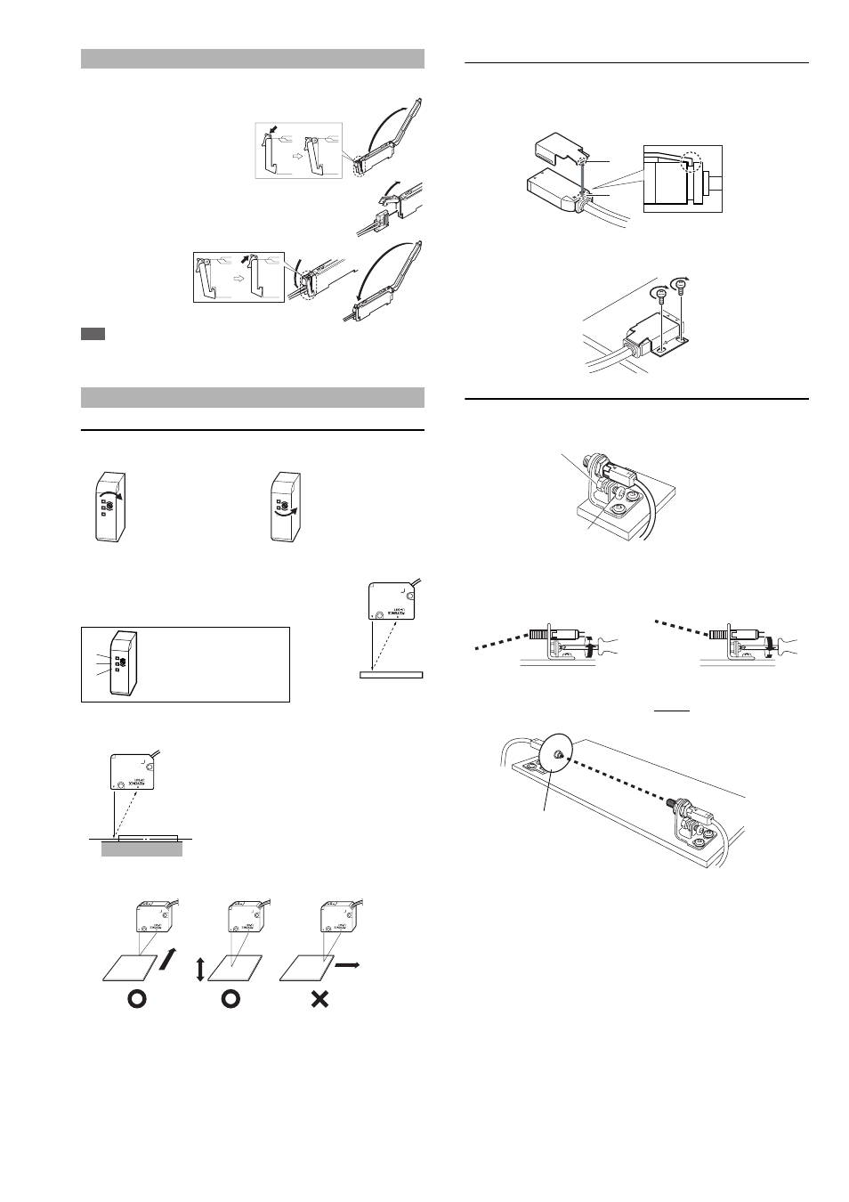
Connecting the Sensor Head and the Amplifier Unit
■ How to connect the amplifier unit and the connector
1
Open the dust cover, and tilt the
hold-lock lever.
2
Raise the hook, and insert the
connector to the very end.
3
Lower the hook
and hook the part
shown in the
figure, and then
raise the hold-lock
lever.
Note
When shortening the sensor head cable, follow the instructions given in the
“Sensor Head Connector Assembly Manual” included with the sensor head.
Mounting and Adjusting the Sensor Head
LV-S31
■ Adjusting the trimmer (detection position)
The detection range can be selected as desired by adjusting the trimmer.
■ Adjusting the center of detection
1
Place the workpiece at the position you want to set as the
center of detection.
2
Turn the trimmer until JUST indicator (2) illuminates in green.
Finer adjustment is possible by looking at the display on the amplifier (page 7).
■ Detecting a height difference
A stable detection is made possible by
adjusting the trimmer so that the middle
point of the height comes to the center of
detection.
■ Movement directions of the workpiece
LV-S41/S41L
Be sure to use the supplied mounting bracket.
1
Press the mounting bracket on the sensor head.
Be sure to hook the A portion of the mounting bracket on the B portion of
the sensor head.
2
Install the sensor head on the flat surface with the M3 screws as shown in
the following figure. (The M3 screw is not an accessory.)
LV-S71/S72
Mount the sensor head such that the letter “T” (on the transmitter) or “R” (on
the receiver) faces upward. The side where the operation indicator illumi-
nates should face upward.
■ Adjusting the beam axis
The angle of the beam axis can be changed upward if the screw indicated by
the arrow is tightened, and downward if loosened.
Adjust the spot to be emitted at the center on the receiver.
The adjustment is facilitated by attaching the beam-axis adjustment cap sup-
plied with the sensor head to the tip of the receiver. Once the adjustment is
complete, remove the beam-axis adjustment cap.
When detecting the target
from a long distance, turn the
trimmer clockwise to adjust.
When detecting the target
from a short distance, turn the
trimmer counterclockwise to
adjust.
F
J
N
F
N
F
J
N
F
N
When (1) illuminates, turn the trimmer
clockwise until (2) illuminates.
When (2) illuminates, the adjustment is
complete.
When (3) illuminates, turn the trimmer
counterclockwise until (2) illuminates.
F
J
N
F
N
(1)
(2)
(3)
Movement
direction
Detecting
object
Detecting
object
Detecting
object
Movement
direction
Movement
direction
A
B
Fixing nut
Beam axis adjusting
screw
Limit the tightening
torque up to 1.2 Nm.
When you want to lower the beam axis
When you want to raise the beam axis
Beam axis adjustment cap
(supplied with the LV-S71)