Specifications, Warranty, Keyence corporation – KEYENCE PZ-G Series User Manual
Page 2: Pz-g-im-e, Indicators, Mutual interference
2
PZ-G-IM-E
Specifications are subject to change without notice.
KEYENCE CORPORATION
1-3-14, Higashi-Nakajima, Higashi-Yodogawa-ku,
Osaka, 533-8555, Japan
PHONE: +81-6-6379-2211
Copyright (c) 2010 KEYENCE CORPORATION. All rights reserved.
11227E 1070-1 96M11227
Printed in Japan
A7WW1-MAN-0069
■
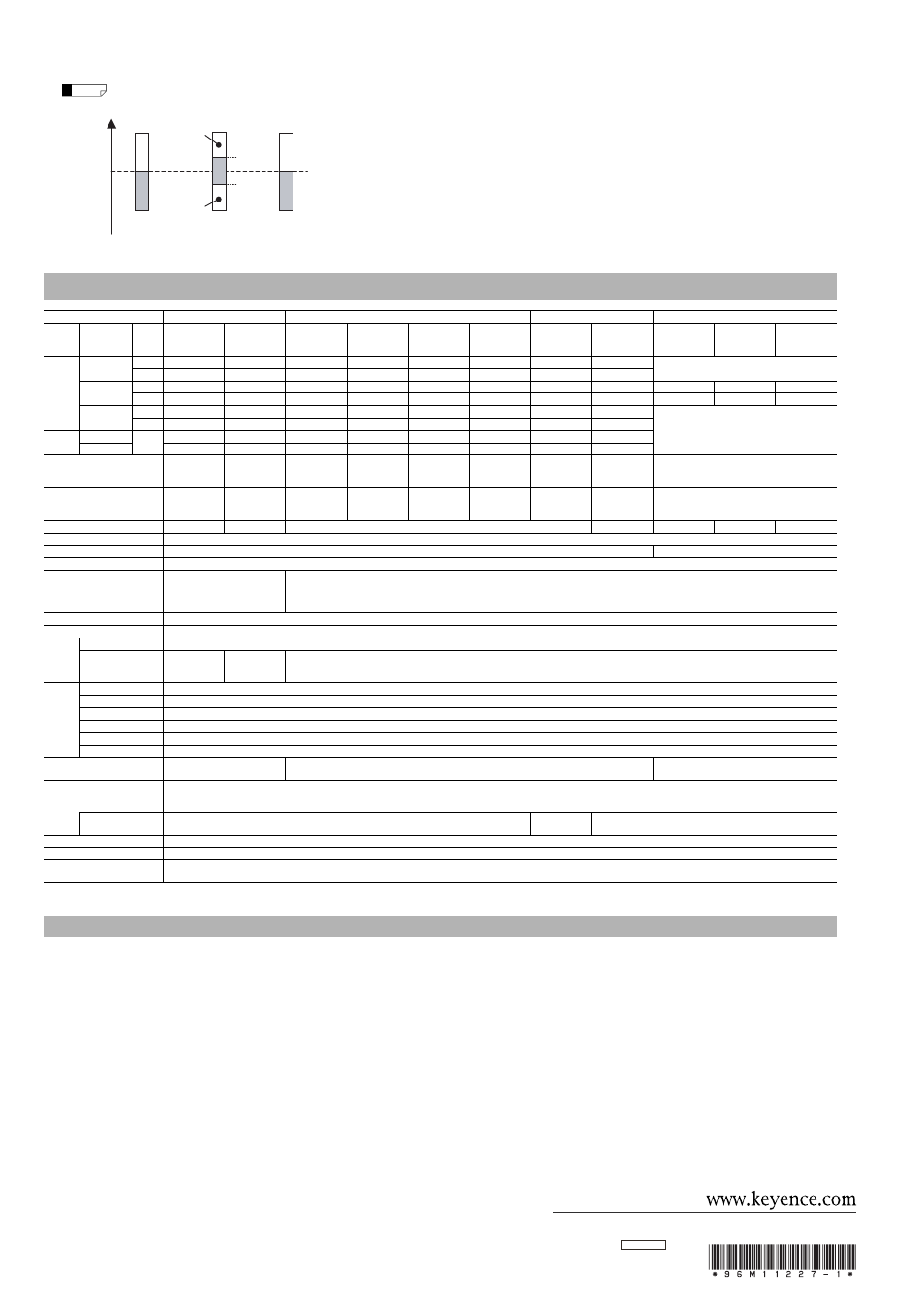
Indicators
The following describes each ON/OFF condition of indicator when LIGHT-ON (L) is set.
When the DARK-ON (D) is set, the output indicator ON/OFF will reverse.
■
Mutual interference
•
For reflective type / retro-reflective type sensors, mutual interference protection can be set for
up to 2 units. However, when the sensors are mounted facing each other, change the angle of
the sensor head to prevent light being emitted into each unit.(The mark detection type does not
include the mutual interference function.)
•
Mutual interference prevention can be set when mounting a polarizing filter attachment
(optional with thrubeam type sensors) (If operation is unstable even after mounting the
polarizing filter, slightly lower the sensitivity.)
•
For more detailed information about mutual interference or attachment, see the PZ-G Series
catalog or contact your nearest KEYENCE office.
*1 The detection distance is measured with the maximum sensitivity.
*2 The cable for the connector type / pigtail quick disconnect type is sold separately. The reflector for the retro-reflective type is sold separately.
KEYENCE products are strictly factory-inspected. However, in the event of a failure, contact your
nearest KEYENCE office with details of the failure.
1. WARRANTY PERIOD
The warranty period shall be for one year from the date that the product has been delivered to
the location specified by the purchaser.
2. WARRANTY SCOPE
(1) If a failure attributable to KEYENCE occurs within the abovementioned warranty period, we will
repair the product, free of charge. However, the following cases shall be excluded from the
warranty scope.
• Any failure resulting from improper conditions, improper environments, improper handling,
or improper usage other than described in the instruction manual, the user’s manual, or the
specifications specifically arranged between the purchaser and KEYENCE.
• Any failure resulting from factors other than a defect of our product, such as the purchaser’s
equipment or the design of the purchaser’s software.
• Any failure resulting from modifications or repairs carried out by any person other than
KEYENCE staff.
• Any failure that can certainly be prevented when the expendable part(s) is maintained or
replaced correctly as described in the instruction manual, the user’s manual, etc.
• Any failure caused by a factor that cannot be foreseen at a scientific/technical level at the
time when the product has been shipped from KEYENCE.
• Any disaster such as fire, earthquake, and flood, or any other external factor, such as
abnormal voltage, for which we are not liable.
(2) The warranty scope is limited to the extent set forth in item (1), and KEYENCE assumes no
liability for any purchaser’s secondary damage (damage of equipment, loss of opportunities,
loss of profits, etc.) or any other damage resulting from a failure of our product.
3. PRODUCT APPLICABILITY
KEYENCE products are designed and manufactured as general-purpose products for general
industries.
Therefore, our products are not intended for the applications below and are not applicable to
them. If, however, the purchaser consults with us in advance regarding the employment of our
product, understands the specifications, ratings, and performance of the product on their own
responsibility, and takes necessary safety measures, the product may be applied. In this
case, the warranty scope shall be the same as above.
• Facilities where the product may greatly affect human life or property, such as nuclear
power plants, aviation, railroads, ships, motor vehicles, or medical equipment
• Public utilities such as electricity, gas, or water services
• Usage outdoors, under similar conditions or in similar environments
E 1040-1
Reference
Green indicator
light
130%*
80%*
Green indicator
light
* For PZ-G62, the upper limit is 107% and the lower limit is 93%.
100%
threshold
value
Received light intensity
Light indicator
(only PZ-G51/52 Series)
Output
Indicator
Stable operation
indicator
Orange
indicator light
Red indicator
light
LIGHT-OFF
LIGHT-OFF
LIGHT-OFF
If the stable operation indicator turns off during operation, readjust or fine-adjust the sensitivity.
Specifications
Type
Thrubeam
Reflective
Retro-reflective
Mark detection
Normal
High-power
Diffuse-reflective
Long-detecting
distance
Diffuse-reflective
Short-detecting
distance
Narrow-view
reflective
Definite
reflective
Long detecting
distance
(with P.R.O. function)
Transparent target
detection
(without P.R.O. function)
Red
Green
Blue
Configuration Cable shape
Output
mode
Rectangular
Cable
NPN
PZ-G51N
PZ-G52N
PZ-G41N
PZ-G42N
PZ-G101N
PZ-G102N
PZ-G61N
PZ-G62N
-
PNP
PZ-G51P
PZ-G52P
PZ-G41P
PZ-G42P
PZ-G101P
PZ-G102P
PZ-G61P
PZ-G62P
M8 connector
NPN
PZ-G51CN
PZ-G52CN
PZ-G41CN
PZ-G42CN
PZ-G101CN
PZ-G102CN
PZ-G61CN
PZ-G62CN
PZ-G10RCN
PZ-G10GCN
PZ-G10BCN
PNP
PZ-G51CP
PZ-G52CP
PZ-G41CP
PZ-G42CP
PZ-G101CP
PZ-G102CP
PZ-G61CP
PZ-G62CP
PZ-G10RCP
PZ-G10GCP
PZ-G10BCP
M12 pigtail quick
disconnect
NPN
PZ-G51EN
PZ-G52EN
PZ-G41EN
PZ-G42EN
PZ-G101EN
PZ-G102EN
PZ-G61EN
PZ-G62EN
-
PNP
PZ-G51EP
PZ-G52EP
PZ-G41EP
PZ-G42EP
PZ-G101EP
PZ-G102EP
PZ-G61EP
PZ-G62EP
Nut
Cable
Bipolar
(NPN+PNP)
PZ-G51B
PZ-G52B
PZ-G41B
PZ-G42B
PZ-G101B
PZ-G102B
PZ-G61B
PZ-G62B
M12 connector
PZ-G51CB
PZ-G52CB
PZ-G41CB
PZ-G42CB
PZ-G101CB
PZ-G102CB
PZ-G61CB
PZ-G62CB
Detecting distance
*1
20 m
40 m
1 m
(30
× 30 cm
white mat paper)
300 mm
(10
× 10 cm
white mat paper)
200 mm
5 to 45 mm
0.1 to 4.2 m
(when R-2L
reflector is used)
0.1 to 1 m
(when R-2L
reflector is used)
8 to 15 mm
Spot diameter
-
-
-
-
Approx.
φ 5 mm
(when the detecting
distance is 100 mm)
Approx.
φ 2 mm
(when the detecting
distance is 40 mm)
-
-
Approx. 1.5
× 4 mm
(when the detecting distance is 10 mm)
Light source (LED)
Red LED
Infrared LED
× 2
Red LED
Infrared LED
Red LED
Green LED
Blue LED
Sensitivity adjustment
1-turn trimmer (230 degrees)
Response time
500 μs
50 μs
Operation mode
LIGHT-ON/DARK-ON, trimmer-selectable
Indicator (LED)
Transmitter: power (orange)
Receiver: output (orange),
stable operation (green),
light (red)
Output (orange), stable operation (green)
Control output
Open-collector 100 mA max. (30 V max.), Residual voltage 1 V max.
Protection circuit
Reverse-polarity protection, over-current protection, output surge absorber
Ratings
Power voltage
10 to 30 VDC, Ripple (P-P): ±10% max, Class 2.
Current consumption
Transmitter: 20 mA
max.
Receiver: 28 mA max.
Transmitter: 25 mA
max.
Receiver: 28 mA max.
34 mA max.
Environmental
resistance
Enclosure rating
IEC,JEM: IP67 / NEMA: 4X,6,12 / DIN: IP69K
Ambient light
Incandescent lamp: 5,000 (lx) max, Sunlight: 20,000 (lx) max.
Ambient temperature
-20
°C to +55°C (No freezing)
Relative humidity
35 to 85
% RH (No condensation)
Vibration resistance
10 to 55 Hz, 1.5 mm double amplitude in X, Y, Z directions, 2 hours each
Shock resistance
1000 m/s
2
in X, Y, Z directions, 6 times each
Interference prevention
2 units
(when polarizing filter attachment is used)
2 units (with the automatic different cycle function)
-
Material
Case, M18 nut (nut type only): reinforced glass polybutylene terephthalate (PBT), Trimmer: reinforced glass polyamide (PA)
Cable (Cable type / pigtail quick disconnect type only): Polyvinyl chloride (PVC), Screw (Case connection): Steel, zinc-nickel plated, Packing (Case connection): Nitrile-butadiene rubber (NBR)
Connector (pigtail quick disconnect type only): Brass-nickel plated, Polybutyleneterephtalate (PBT), Polyvinyl chloride (PVC)
Lens cover
Polyarylate (PAR)
Acrylic plastic
(PMMA)
Polyarylate (PAR)
Tightening torque
Rectangular type (side screw part): 0.5 N·m max. Nut type (front M18 part): 1.0 N·m max., (side slot part): 0.5 N·m max.
Accessory
*2
Instruction manual, M18 nut x 2 (nut thrubeam type), M18 nut x 1 (other nut types)
Weight
Rectangular cable type: Approx. 60 g (Approx. 50 g for thrubeam transmitter), Rectangular M8 connector type: Approx 10 g, rectangular M12 pigtail quick disconnect type: Approx. 30 g
Nut type cable type: Approx. 65 g (Approx. 55 g for thrubeam transmitter), Nut type M12 connector type: Approx 15 g
WARRANTY