Cub Cadet 600 series User Manual
Page 21
500 and 600 SERIES 2-STAGE SNOW THROWER
17
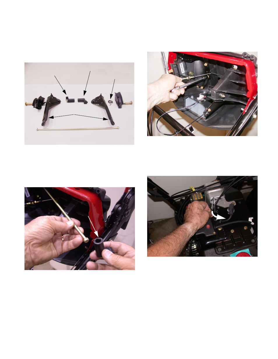
15.4. Carefully release the tension from the torsion
spring as the bolt withdraws. Some models are
equipped with an auger lock, or one hand opera-
tion the following image shows the parts of the
auger lock feature See Figure 15.4.
15.5. repeat steps15.1,15.2,and 15.3 to disconnect
and remove the traction control lever.
15.6. Detach the pivot rod from the clutch lock cam.
NOTE: The flats at each end of the pivot rod fit
into the “D” hole in the cam lock.
Figure 15.4
Pivot Rod
Engagement handles
Clutch Lock Cam
Lock Plate
Torsion Spring
Figure 15.6
“D” hole
15.7. Remove the (6) screws that fasten the joystick to
the dash with a 3/8” socket.a 6” extension may
be handy at this time. See Figure 15.7.
15.8. The Joystick will drop down towards the bottom
of the dash panel.
15.9. Slide the cables from the cable retainer posi-
tioned on the engine. See Figure 15.9.
15.10.Slip the bow tie cotter pin from the clevis pin that
holds the pivoting assembly to the support
bracket. See Figure 15.10.
Figure 15.7
Figure 15.9