Axle assembly removal(600 series, non-steerable – Cub Cadet 600 series User Manual
Page 11
500 and 600 SERIES 2-STAGE SNOW THROWER
7
7.9.
Remove the 5/16” hex screw securing the barrel
side of the cable.
NOTE: The bracket securing the cable to the
shift lever is (2) pieces
7.10. Examine the removed cable: If it failed because
of something other than normal wear, identify
and correct the cause before returning the snow
thrower to service.
7.11. Install new cable by reversing the removal pro-
ceedure.
7.12. Run/test/Adjust the speed control cable before
returning to service.
7.13. The torsion spring to the maintains continuous
tension on the speed control cable.
Figure 7.9
Figure 7.13
TORSION SPRING
8.
AXLE ASSEMBLY REMOVAL(600 SERIES,
NON-STEERABLE
8.1.
With the engine stopped and allowed to cool dis-
connect the spark plug wire and ground it to the
engine.
8.2.
Confirm that the fuel level is low enough to pre-
vent spillage through the gas cap vent, or seal
the vent with a plastic bag between the cap and
the filler neck
8.3.
Carefully tip the snow thrower forwards so it rest
on the auger housing
8.4.
Remove the bottom access panel.
See Figure 8.4.
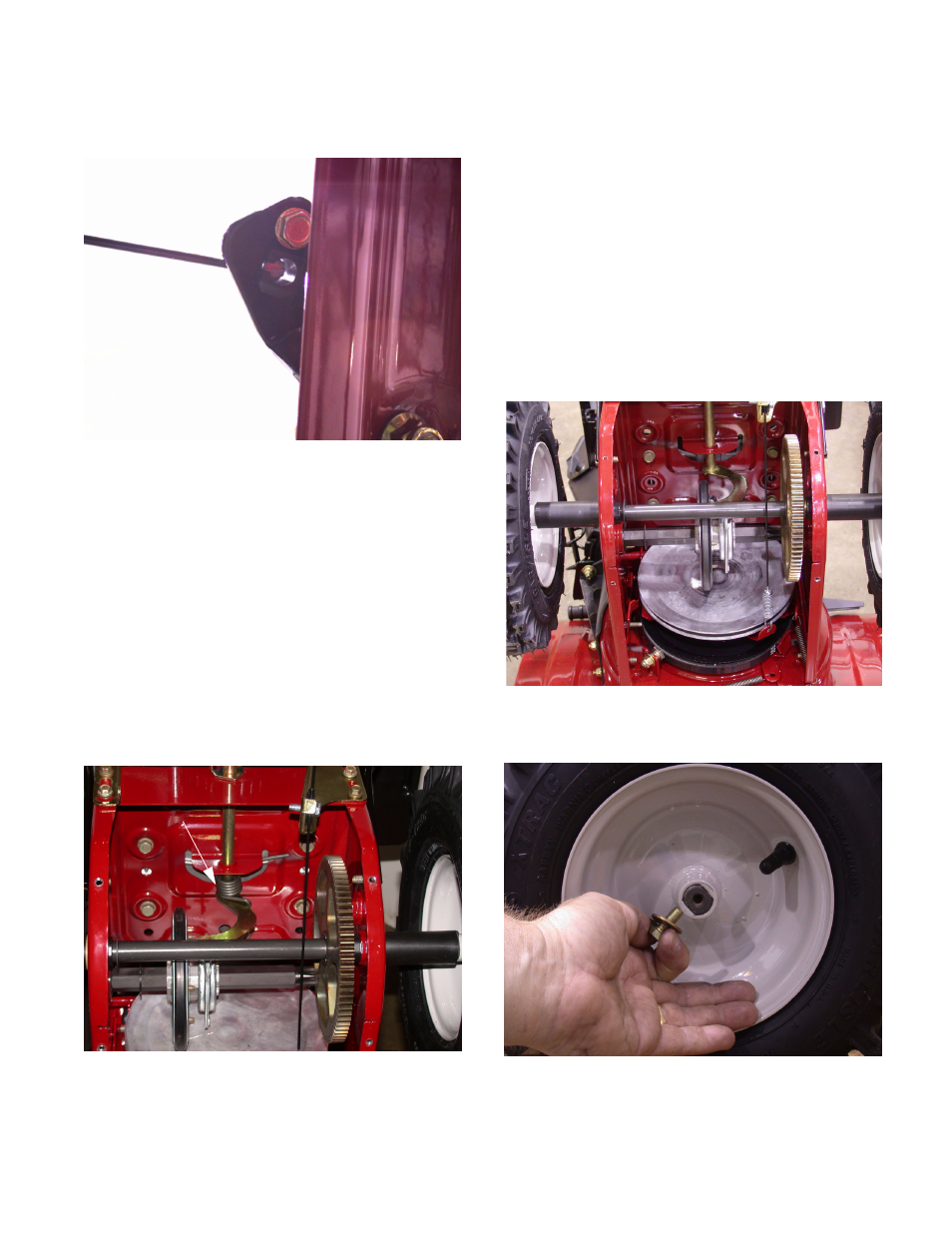
8.5.
Remove the wheels with a 1/2” socket.
NOTE: The end of the axle shaft are double - D.
Figure 8.4
Figure 8.5