Auger assembly – Cub Cadet 600 series User Manual
Page 18
500 and 600 SERIES 2-STAGE SNOW THROWER
14
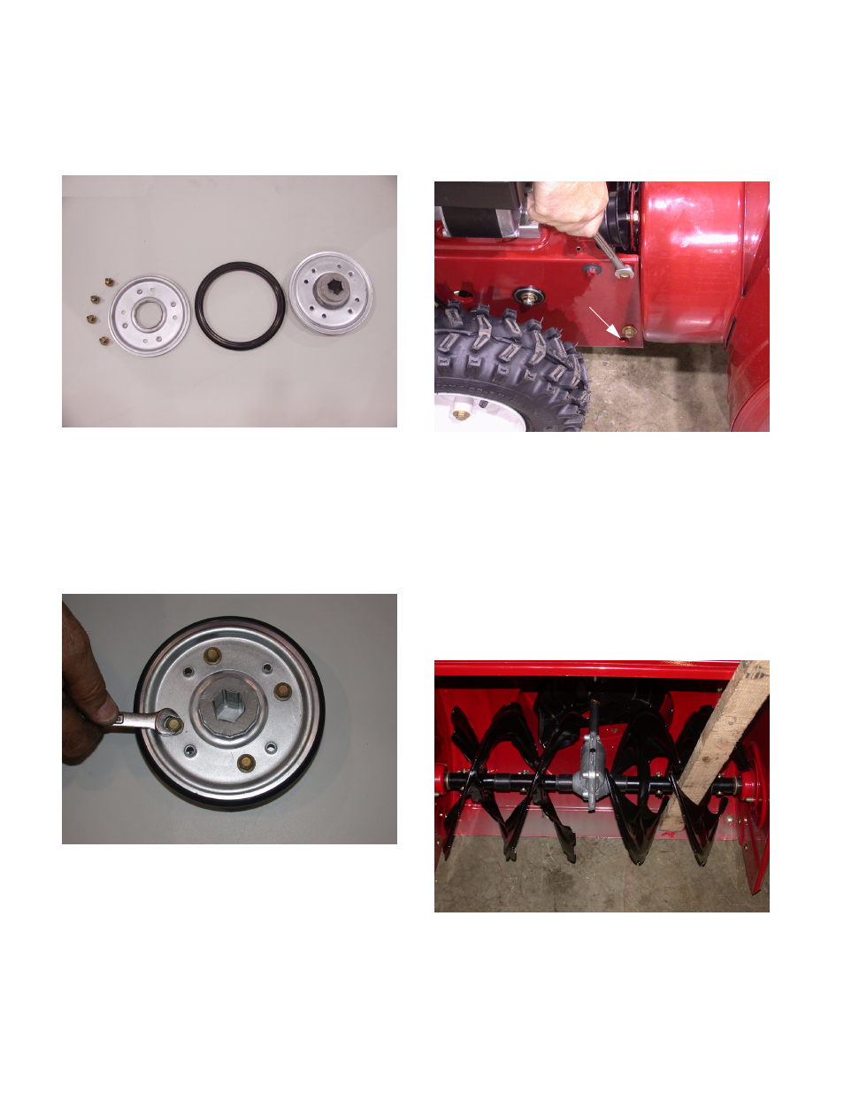
13.3. Examine the removed parts: If it failed because
of something other than normal wear, identify
and correct the cause before returning to ser-
vice. See Figure 13.3.
13.4. Install the rubber friction wheel by reversing the
removal procedure.
13.5. Run/test the snow thrower before returning to
service.
13.6. When reassembling the rubber wheel tighten the
screw in an alternating order. See Figure 13.6.
13.7. When installing the new friction wheel be sure
that the rubber ring is secure within the wheel.
NOTE: use a high quality grease suitable for
used in sub-zero temperatures on the hex shaft
to allow the friction wheel assembly to move
across the hex shaft freely.
14.
AUGER ASSEMBLY
14.1. Remove the screws that fasten the auger hous-
ing to the rear portion of the snow thrower with a
1/2” wrench. See Figure 14.1.
NOTE: After the 4 screws (2 on each side) have
been remove the 2 parts of the snow thrower will
open up like a clam shell there is a pivot point
stamped onto each side of the frame.
14.2. Work the auger belt off of the auger pulley.
14.3. Separate the auger housing from the drive hous-
ing.
14.4. Use a block of wood to prevent the augers from
turning. See Figure 14.4.
Figure 13.3
Figure 13.6
1
2
3
4
Figure 14.1
Pivot point
Figure 14.4