Drive shaft assembly (600 series), 500 drive assembly (500 series steerable) – Cub Cadet 600 series User Manual
Page 14
500 and 600 SERIES 2-STAGE SNOW THROWER
10
10.
DRIVE SHAFT ASSEMBLY (600 SERIES)
10.1. Remove the axle assembly as described in axle
assembly removal
10.2. Pry off the E-ring off the left side of unit holding
the Drive shaft assembly in. See Figure 10.2.
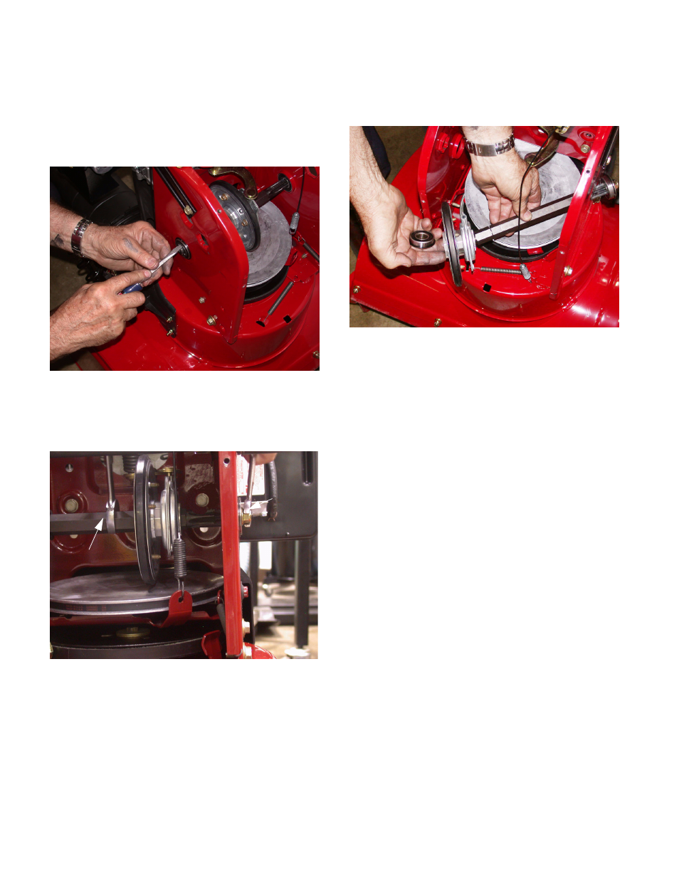
10.3. Remove the Bolt from the end of the shaft secur-
ing the hex shaft to the frame with a 9/16”
wrench See Figure 10.3.
NOTE: to prevent the hex shaft from turning
while removing the exterior screw hold the hex
shaft with a 13/16” wrench.
10.4. Rotate the friction wheel assembly forward to
free the collar from the pin on the shift assembly.
10.5. Maneuver the shaft partially through the wheel
drive frame then tilt the assembly forward to free
it from the housing. See Figure 10.5.
10.6. Examine the remove parts: if any failed because
of something other that normal wear, identify and
correct the cause before returning the snow
thrower to service.
10.7. Install the drive shaft assembly by reversing the
removal procedure.
10.8. Run/ test the drive shaft before returning the
snow thrower to service
11.
500 DRIVE ASSEMBLY (500 SERIES STEER-
ABLE)
11.1. Stop engine allow to cool disconnect the spark
plug and ground it to the engine.
11.2. Confirm that the fuel level is low enough to pre-
vent spillage through the gas cap vent, or seal
the vent with a plastic bag between the fuel cap
and the filler neck.
11.3. Carefully tip the snow thrower forward so it rests
the auger housing.
11.4. Remove the access panel with 3/8” socket.
11.5. Remove both wheels with a 1/2” socket.
11.6. Loosen and remove the screw and nut that holds
the adjustment on the shifter cable.
Figure 10.2
Figure 10.3
13/16” Wrench
9/16”
Wrench
Figure 10.5