Series 5000 – Cub Cadet 5000 Series User Manual
Page 28
Series 5000
24
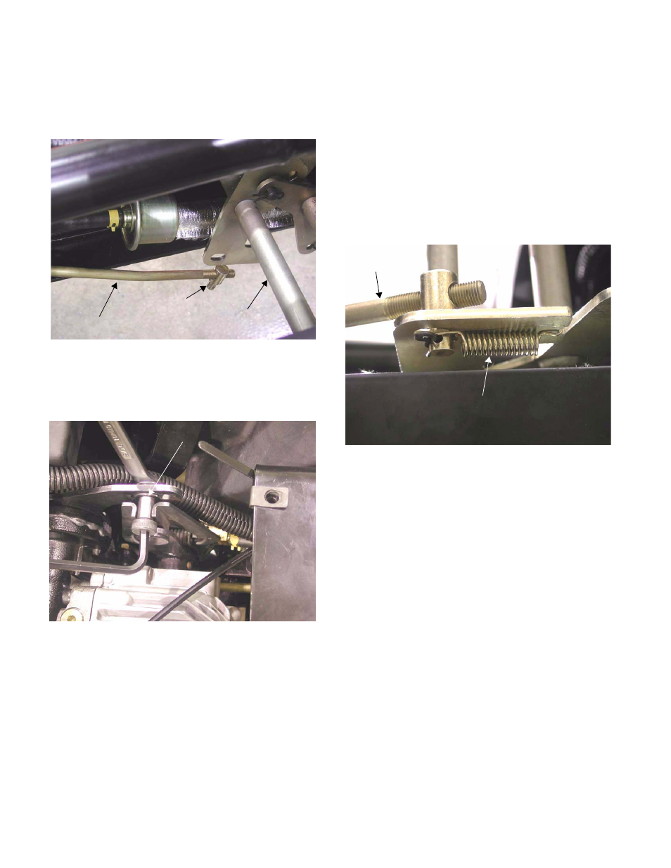
8.6.
Disconnect the ferrule at the front of the hydro
control rod from the arm on the pedal shaft by
removing the hairpin clip and removing the small
pre-load spring.
8.7.
Loosen the nut and neutral adjustment shoulder
screw using a 9/16” wrench and a 1/4” allen
wrench.
8.8.
Start the engine, and engage the differential
lock.
NOTE: It is necessary to engage the differential
lock to make both wheels turn in unison, clarify-
ing the presence and direction of drive motion.
8.9.
Slide the neutral adjustment shoulder screw for-
ward or backward to eliminate any wheel motion.
8.10. When wheel motion has stopped, turn-off the
engine and tighten the neutral adjustment shoul-
der screw and nut.
8.11. Re-start the engine and confirm that the adjust-
ment did not shift as it was tightened.
8.12. Turn the engine off.
8.13. Operate the drive pedals to confirm freedom of
movement and operation of the hydraulic
damper.
8.14. Set the parking brake.
8.15. Thread the ferrule up or down the hydro control
rod until it fits into the slot in the arm on the
pedal shaft, resting against the front of the slot.
8.16. Secure the ferrule using the hairpin clip and pre-
load spring.
8.17. Start the engine and confirm that the wheels do
not creep with the brake released, the differential
lock engaged, and neither drive pedal (forward
or reverse) depressed.
8.18. Install the seat.
8.19. Remove the jumper wire from the seat safety
harness, and reconnect the seat safety
switch.
8.20. Test the operation of the reverse safety switch
and seat safety switch.
8.21. Lower the tractor to the ground.
Figure 8.6
Hydro control rod
Ferrule
Pedal shaft
assembly
Figure 8.7
Neutral Adjustment shoulder screw
Figure 8.15
Extension spring
Hydro control
rod