Series 5000 – Cub Cadet 5000 Series User Manual
Page 22
Series 5000
18
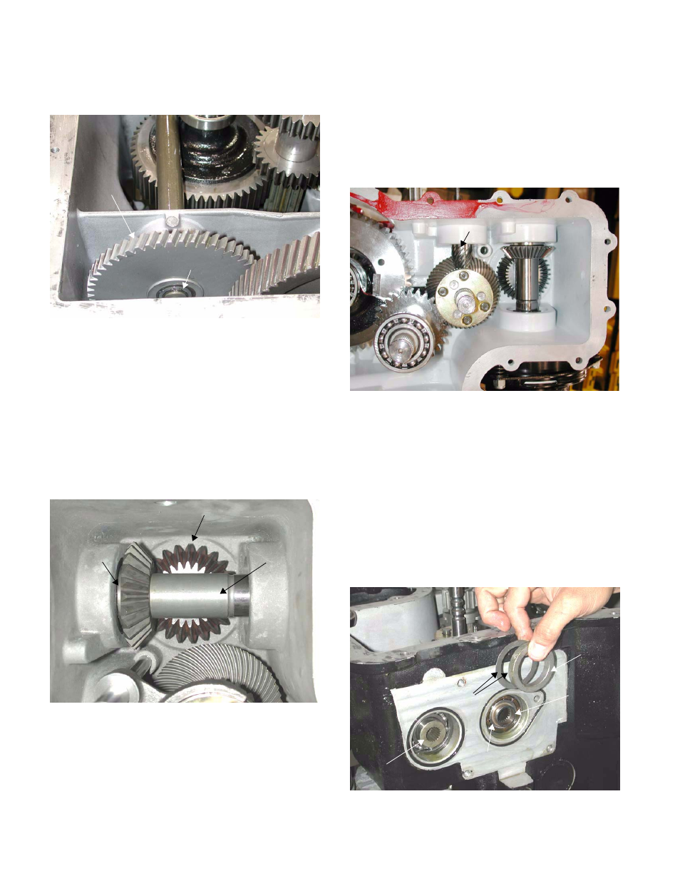
5.26. The front 2000 PTO shaft drive gear can be
removed as the shaft slides forward.
5.27. The PTO system is driven by a shaft that passes
through the hydrostat, providing power to the
variable displacement pump in the hydro and the
charge pump in the hydro.
5.28. The direct-driven output shaft from the hydro
(passing through the variable displacement
pump) drives the auxiliary pump (mounted on
the transmission housing) through a set of bevel
gears. The same shaft drives the electric PTO
clutch.
5.29. The lower output shaft from the hydro. is driven
by the fixed displacement pump in the hydro.
The lower shaft responds to the output of the
variable displacement pump with changes in
speed and direction. The variable displacement
pump responds to control inputs from the opera-
tor.
5.30. The input spiral pinion gear that is driven by the
lower output shaft of the hydro is suspended on
its own ball bearing. A stem on the spiral pinion
gear passes through the bearing, and is secured
there by a retaining ring.
5.31. The ball bearing is held in the base of its bore by
the hydrostat. A spacer and a flat washer
between the body of the hydro. and the bearing
set the end play of the gear.
NOTE: Because backlash between the input spi-
ral pinion gear and the spiral bevel gear is a
function of each gears’ end play, different thick-
nesses of flat washer are used to adjust the end
play (backlash) of the spiral pinion gear. Flat
washers are available in thicknesses of .005”,
.015”, and .030”.
Figure 5.26
Retaining ring
2000 PTO
pinion gear (front)
Figure 5.28
PTO
Input
Shaft
Bevel gear
driving auxiliary
pump
Bevel gear
PTO input shaft
of hydro
driving off
fixed
displacement
motorshaft
Figure 5.30
Input spiral pinion gear
off of variable displacement
pump shaft
Figure 5.31
Flat
washers
Spacer
PTO
input
shaft
shoulder
of
spiral
bevel
gear
snap ring