Series 5000 – Cub Cadet 5000 Series User Manual
Page 25
Series 5000
21
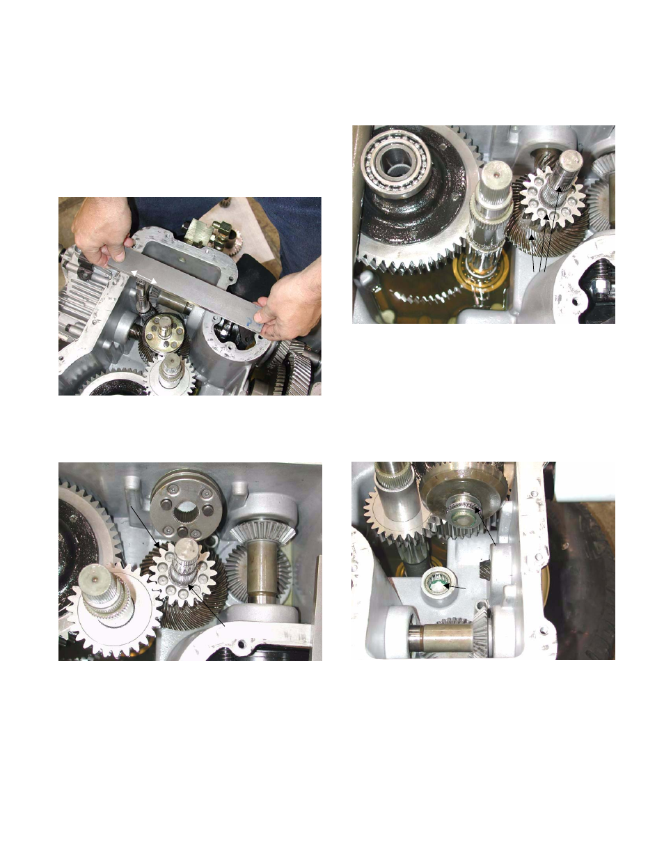
5.39. The shift yoke can be removed from the high -
low actuator shaft by removing the rotor clip.
NOTE: Match mark the yoke and shaft before
they are separated. When they are installed, the
yoke must engage the shift collar, and the flat on
the end of the actuator shaft must be parallel
with the top and bottom surfaces of the transmis-
sion.
5.40. The low range (19 tooth) spur gear is held onto
the primary shaft by a spiral retaining ring.
5.41. If it is necessary to remove the primary shaft,
carefully pry the input spiral pinion gear back.
NOTE: BDU 21L Hydrostatic pump previously
removed.
NOTE: The spiral bevel gear is a keyed press fit
onto the primary shaft.
Actuator shaft
orientation
Figure 5.39
Spiral retaining ring
Low range
spur
gear
Figure 5.40
5.42. Lift the primary shaft, low range (19 tooth) spur
gear, and spiral bevel gear out of the transmis-
sion housing together.
5.43. The thrust pack (radial needle bearing sand-
wiched between two ground flat washers) that
fits between the spiral bevel gear and the trans-
mission housing comes out with the shaft.
5.44. The roller bearing that the nose of the primary
shaft pilots into in the transmission housing must
be removed using a blind bearing puller.
Figure 5.42
Primary
shaft, spur
gear and
spiral bevel gear
Radial needle
bearing
Roller bearing
Figure 5.44