Checkline CAP-TT01 User Manual
Page 6
Series TT01 Digital Cap Torque Testers
User’s Guide
5
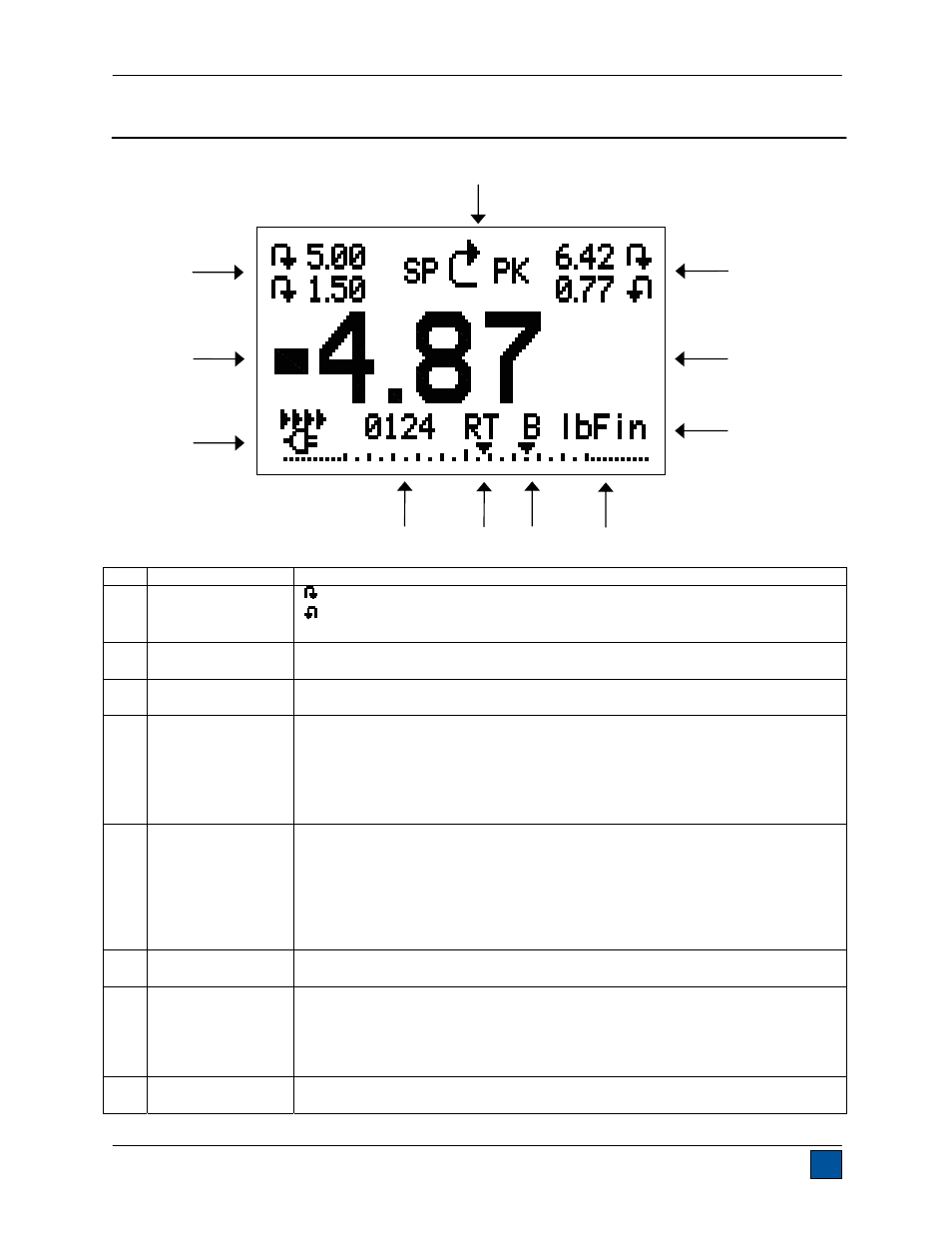
4 HOME SCREEN AND CONTROLS
4.1 Home Screen
No. Name
Description
1
Measurement
direction
indicator
– indicates clockwise direction
– indicates counter-clockwise direction
These indicators are used throughout the display and menu.
2 Peaks
The maximum measured clockwise and counter-clockwise readings. These
readings are reset by pressing ZERO or by powering the tester off and on.
3 Primary
reading
The current displayed load reading. See Operating Modes section for
details.
4 Units
The current measurement unit. Abbreviations are as follows:
ozFin – Ounce-inch
lbFin – Pound-inch
kgFcm – Kilogram-centimeter
Ncm – Newton-centimeter
Nm – Newton-meter
5 Load
bar
Analog indicator to identify when an overload condition is imminent. The bar
increases either to the right or left from the midpoint of the graph. Increasing
to the right indicates clockwise load, increasing to the left indicates counter-
clockwise load. If set points are enabled, triangular markers are displayed for
visual convenience. This indicator reflects the actual load, which may not
correspond to the primary reading (depends on operating mode). The ZERO
key does not reset the load bar. See Operating Modes section for details.
6
Break Detection
On/Off
The letter “B” appears if the Break Detection function is enabled. Refer to the
Break Detection section for details.
7 Mode
The current measurement mode. Abbreviations are as follows:
RT – Real Time
PCW – Peak Clockwise
PCCW – Peak Counter-clockwise
See Operating Modes section for details about each of these modes
8
Number of stored
data points
The number of stored data points in memory, up to 1000. Displayed only if
Memory Storage is enabled for the DATA key.
1
2
4
5
6
9
10
11
3
7
8