Checkline CAP-TT01 User Manual
Page 19
Series TT01 Digital Cap Torque Testers
User’s Guide
18
13 CALIBRATION
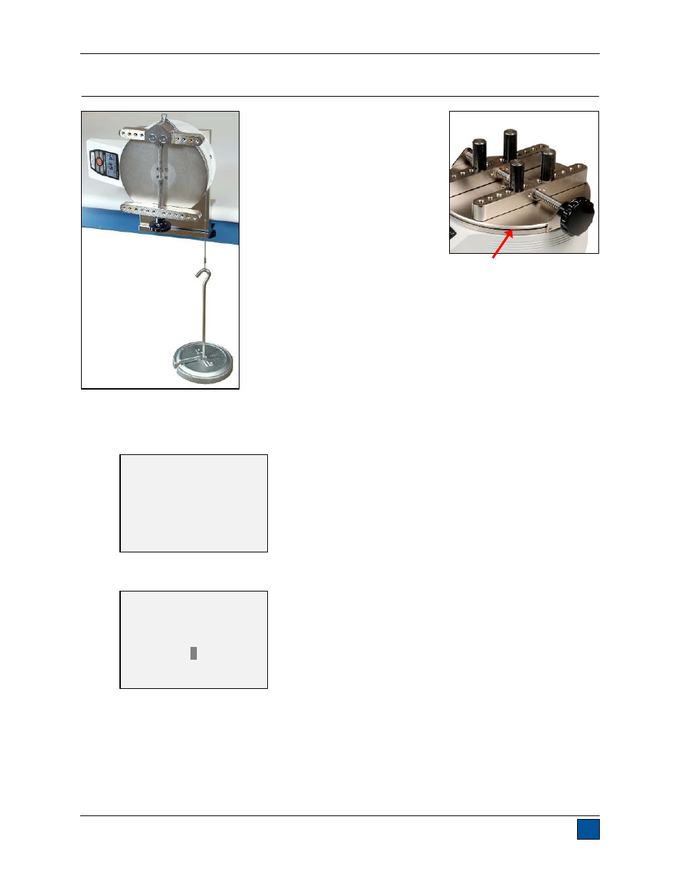
13.1 Initial Physical Setup
The TT01 should be mounted to a
fixture rugged enough to withstand a
load equal to the full capacity of the
tester. Suitable calibration equipment
is required, and caution should be
taken while handling such equipment.
The AC1036 calibration kit is available
from Mark-10, shown at left.
Note the circular groove in the top
plate, shown at right, which
accommodates a cable for suspension of deadweights. The AC1036
calibration kit includes a cable with a diameter of 0.063 in [1.6 mm] for
insertion into this groove. The cable radius plus the circular groove
radius is equal to 3.333 in [84.66 mm]. Commonly available Imperial
deadweights may, therefore, be employed to achieve full scale
Imperial (i.e. lbFin) loads. For example, a 15 lb load multiplied by 3.333
in. will produce 50 lbFin of torque.
Metric unit calibrations are also possible through the configurable
calibration procedure described below:
13.2 Calibration Procedure
1. Select
Calibration from the menu. The display appears as follows:
2. Press
DIRECTION to invert the display, if desired. ENTER to continue. The display appears as
follows:
The tester can be calibrated at up to 10 points in each direction. Enter the number of calibration
points for each direction (clockwise and counter-clockwise). At least one point must be selected
for each direction.
Note: To achieve the accuracy specification of ±0.3%, it is recommended to calibrate the tester at
5 or more even increments in both directions. For example, an MTT01-50 should be calibrated at
10, 20, 30, 40, and 50 lbFin loads in each direction.
CALIBRATION
To invert the
display, press the
DIRECTION button,
then press ENTER.
CALIBRATION
Enter # cal points
(1 to 10)
Clockwise:
5
Counter-clockwise:
5