Suitable headrest for installation, Identify all leads, Installation – Panasonic CY-V7100U User Manual
Page 28: Continued)
Attention! The text in this document has been recognized automatically. To view the original document, you can use the "Original mode".
Installation
(continued)
□ Before Installation
Warning
• TO AVOID RISK OR SERIOUS INJURY OR POSSIBLE
VIOLATION OF LAWS DO NOT INSTALL WHERE VISI
BLE TO THE DRIVER. Do not install the monitor in a
location which obstructs driving, visibility or which is
prohibited by applicable laws and regulations. If the
monitor is installed in a location which obstructs for
ward visibility or operation of the air bag or other safety
equipment or which interferes with operation of the car,
it may cause an accident.
• Never use bolts or nuts from the car's safety devices for
installation. If bolts or nuts from the steering wheel,
brakes or other safety devices are used for installation of
the monitor, it may cause an accident.
• Attach the vmes correctly. If the wiring is not correctly
performed, it may cause a fire, failure of electrical equip
ment and-or an accident. In particular, be sure to run
and secure the lead wire so that it does not get tangled
with a screw or the moving portion of a seat rail.
• Use with 12 V DC negative ground car. This unit is only
for use with a 12 V DC negative ground car. it cannot be
used in large trucks or diesel cars which are 24 V DC
cars. If it is used in the wrong type of car, it may cause a
fire or an accident.
* Use the .specified fuse. 8e sure to al'ways use the
specified fuse, i’ a fuse other than the specihed
fuse is used, it may cause a fire or an accideoi,
• Oc not damage the cord by pmching or puibna it
Do not puli or damage toe cord, d toe cord t$ cot
treated properiy. it
wiil short out or be severed and
may cause a fire ot an accident.
□ Required Tools
You’ll need a screwdriver and the following:
1 2 V D C
Electrical
Side-Cut
Test Bulb
Tape
Pliers
Q
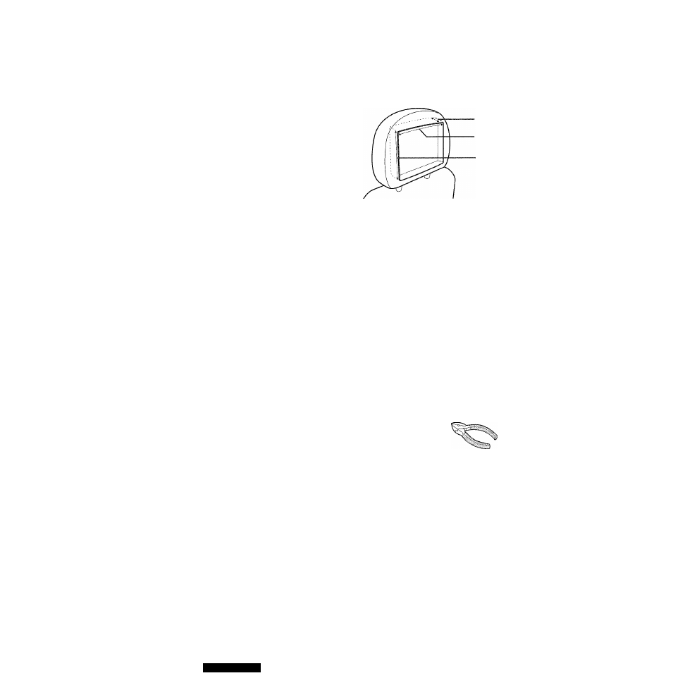
□ Suitable Headrest for Installation
f9/i6" (40 mm)
7W (188 mm)
5V2" (140 mm)
□ Identify All Leads
The first step in installation is to identify all the car wires
you’ll use when hooking up your LCD monitor.
As you identify each wire, we suggest that you label it
using masking tape and a permanent marker. This will help
avoid confusion when making connections later.
Note:
Do not connect the power connector to the display
unit until you have made all connections. It there are no
plastic caps on the hooking wires, insulate all exposed
leads with electrical tape until you are ready to use them.
Identify the leads in the following order.
Power Lead
It your car has a radio or is pre-wired for one:
Cut the connector wires one at a time from the plug (leav
ing the leads as long as possible) so that you can work
with individual leads. Turn the ignition on to the accessory
position, and ground one lead of the test bulb to the chas
sis.
□
II
Touch the other lead of the test bulb to each of the exposed
wires from the cut radio connector plug. Touch one wire at
a time until you find the outlet that causes the test bulb to
light.
Now turn the ignition off and then on. If the bulb also turns
oft and on, that outlet is the car power lead.
If your car is not wired tor an audio unit:
Go to the fuse block and find the fuse port for radio
(RADIO) accessory (ACC) or ignition (IGN).
Battery Lead
If your stereo unit has a yellow lead, you will need to locate
the car's battery lead. Otherwise you may ignore this pro
cedure. (The yellow battery lead provides continuous
power to maintain a clock or other functions.)
If your car has a radio or is pre-wired for one:
With the ignition and headlights oft, identify the car battery
lead by grounding one lead of the test bulb to the chassis
2 8
CY-V7100U