Configuring a modem, Figure b-1, Table b-1 – Cisco 4490 User Manual
Page 80
Appendix B Connecting a Modem to the GSS 4490 Console Port
Configuring a Modem
B-2
Cisco Global Site Selector 4490 Hardware Installation Guide
78-15755-02
Configuring a Modem
You must configure the modem before you can connect it to the GSS 4490. You
can connect the modem to a terminal or a PC using a terminal emulation program,
such as Hyperterminal. If you connect the modem to the COM port on a PC, you
need the following cable and connectors:
•
RJ-45-to-RJ-45 rolled cable
•
RJ-45-to-DB-25 modem adapter
•
DB-9-to-RJ-45 terminal adapter
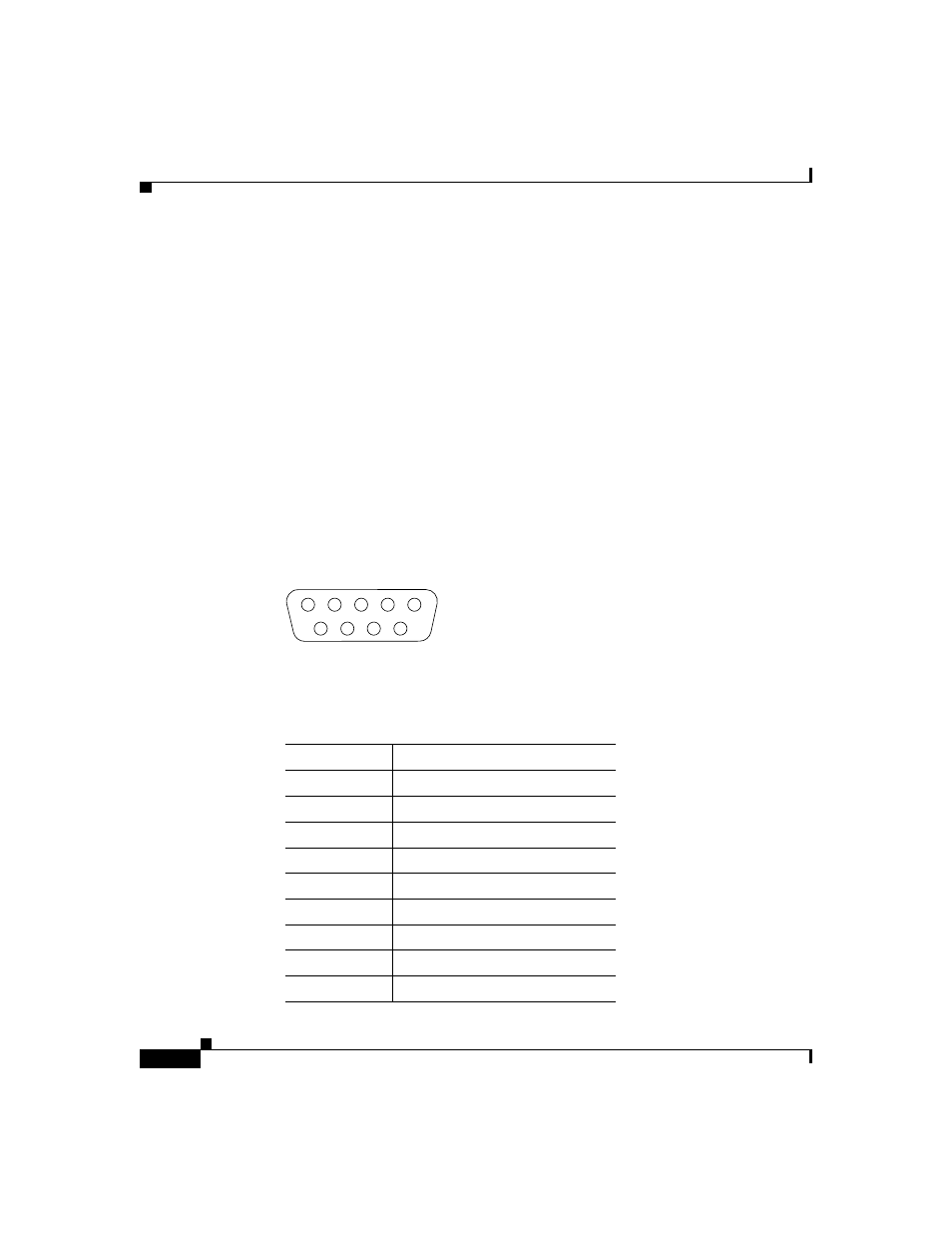
shows the pin number assignments for the 9-pin, male D-shell console
port connector on the back of the GSS 4490. These pin number assignments
conform to the industry standard.
Figure B-1
Console Port Connector
connector pinouts for the GSS 4490 console port.
1
5
6
9
83193
Table B-1
Console Port Connector Pinouts
Pin Number
Signal Name
1
DCD (Data Carrier Detect)
2
RD (Receive Data)
3
TD (Transmit Data)
4
DTR (Data Terminal Ready)
5
SG (Signal Ground)
6
DSR (Data Set Ready)
7
RTS (Request to Send)
8
CTS (Clear to Send)
9
RI (Ring Indicator)