45 assembly of the throttle linkage, No.7, No.6 – OFNA Racing Jammin X2 Buggy User Manual
Page 23
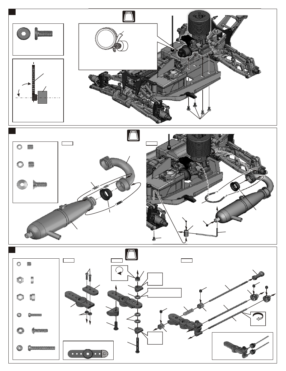
45
ASSEMBLY OF THE THROTTLE LINKAGE
Step 1
Step 2
*Cut off the servo saver as shown.
94033
3x3mm
Set Screw
.....x4
2mm
Nut
.....x2
40060
Nylon Nut
.....x1
2x8mm
Screw
2.6x18mm
Screw
.....x2
.....x1
30661
30802
40060
2mm
40617
40617
30802
2x8mm
*Adjust the height with
3x6.4x1mm washer.
Ensure
Free
Movement
Do Not
Over Tighten
Ensure
Free
Movement
2.6x18mm
94003
3x10mm
Hex Screw
.....x1
3x10mm
36140
Rotate
Direction
Step 3
3x3mm
30172
3x3mm
3x3mm
30172
30172
30531
30802
* Throttle servo horn after assembly.
10300
10300
30802
30802
43
44
ASSEMBLY OF THE ENGINE ONTO CHASSIS
ASSEMBLY OF THE MANIFOLD AND MUFFLER
10114
5mm
Engine Mount Screw
.....x4
10114
4x10mm
40549
41050
5x4mm
Spur Gear
Clutch Bell
*Loose or tighten 3x20mm cap
screw and 5x10mm hex screw
to align spur gear and clutch
bell gear to 90 degree.
90 degree
10120
4x4mm
94026
4x10mm
Flat Head
Hex Screw
.....x1
94034
4x4mm
Set Screw
.....x1
94036
5x4mm
Set Screw
.....x1
Step 2
*Use notebook paper to set gear backlash between
spur gear and clutch bell gear; apply pressure
while tightening the engine.
*If the space is not correct, the spur gear will be
damaged.
Notebook paper
Step 1
NO.7
BAG
NO.7
BAG
NO.6
BAG
10128
Manifold(Option)
10128
Muffler(Option)
97500
1/8 Silicone
Seal(Option)
95701
1/8 Spring(Option)
97500
1/8 Silicone
Seal(Option)