Pilz S1MS 24VAC/DC 2c/o User Manual
Page 2
- 2 -
Description de l’appareil
Inséré dans un boîtier S-95, le relais de
surveillance de température est disponible
en 5 versions pour les tensions alternatives
et une version pour le tension continue et
alternatif.
Particularités:
• Contacts de sortie:
2 OF (inverseurs)
• Circuit de mesure pour le câblage d’une
sonde CTP
• Réarmement automatique
• LEDs de visualisation présence tension
d'alimentation
• LED d’indication du défaut
Le relais répond aux exigences de sécurité
suivantes:
• Indication du défaut par retombée du
relais de sortie
• Protection de l’installation garantie en cas
de:
- défaillance tension d’alimentation
- défaillance bobine
- défaut soudure
Description
The Thermistor Protection Relay is enclosed
in a S-95 housing. There are 5 versions
available for AC operation and 1 version for
DC and AC operation.
Features:
• Relay contacts:
2 auxiliary contacts (2 C/O)
• Measuring circuit for connection of a
temperature sensor (PTC-resistance)
• Monitoring of the temperature sensor for
short circuit
• Automatic reset
• LED display for operating voltage
• error indicating LED
The unit complies with the following safety
requirements:
• Normally energised mode
• Protection of the monitored unit is
maintained in the following cases:
- Loss of voltage
- Coil defect in a relay
- Cable break
Gerätebeschreibung
Das Temperaturüberwachungsrelais ist in
einem S-95-Gehäuse untergebracht. Es
stehen 5 Varianten für den Betrieb mit
Wechselspannung und eine Variante für
den Betrieb mit Gleich- und Wechsel-
spannung zur Verfügung.
Merkmale:
• Relaisausgänge:
2 Hilfskontakte (2 U)
• Messkreis für den Anschluss eines
Temperaturfühlers (PTC- Widerstand)
• automatischer Reset
• LED zur Versorgungsspannungsanzeige
• LED zur Störungsanzeige
Das Gerät erfüllt folgende Sicherheitsanfor-
derungen:
• Funktion nach dem Ruhestromprinzip
• Schutz der zu überwachenden Anlage ist
gewährleistet bei:
- Spannungsausfall
- Spulendefekt
- Leiterbruch
* Isolation zum nicht markierten Bereich und der
Relaiskontakte zueinander: Basisisolierung
(Überspannungskategorie III), sichere Trennung
(Überspannungskategorie II)
* Insulation between the non-marked area
and the relay contacts: Basic insulation
(overvoltage category III), safe separation
(overvoltage category II)
* Isolation de la partie non sélectionnée par
rapport aux contacts relais : isolation
basique (catégorie de surtensions III),
isolation galvanique (catégorie de
surtensions II)
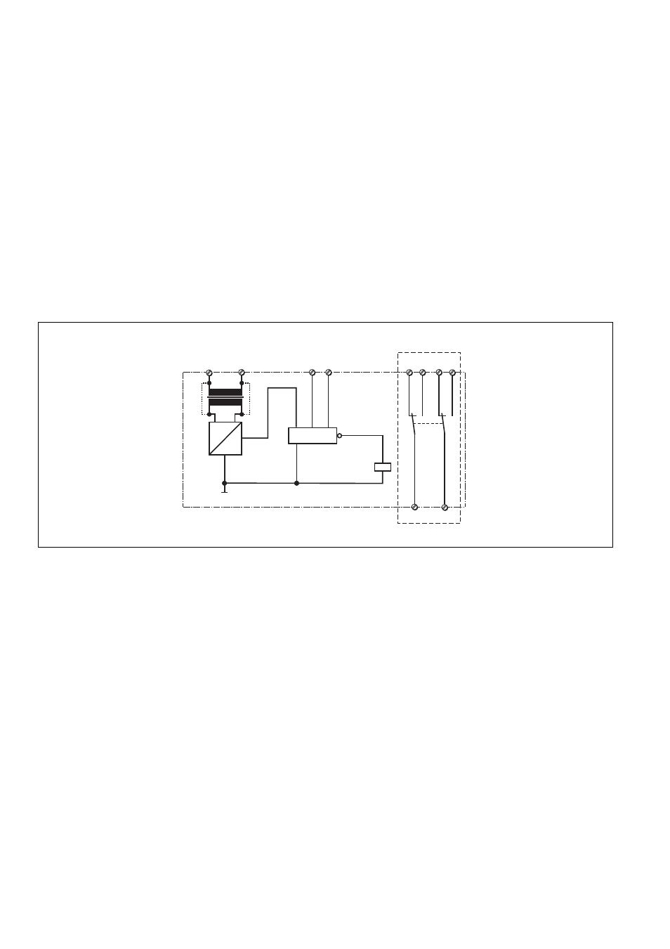
Fig. 1: Schematisches Schaltbild
S1MS
G1
F1
K1
T1
T2
K1
J > NAT
Messkreis
Measuring Circuit
Circuit mesure
+
~
=
A2
(-)
A1
(+)
B
U
12 14
11
22 24
21
*
Fig. 1: Wiring diagram
Fig. 1: Schéma interne