Pilz PSEN 2.2p-21/LED/8mm 1 switch User Manual
Page 3
- 3 -
Schaltabstände/Switching distances/Distance de commutation
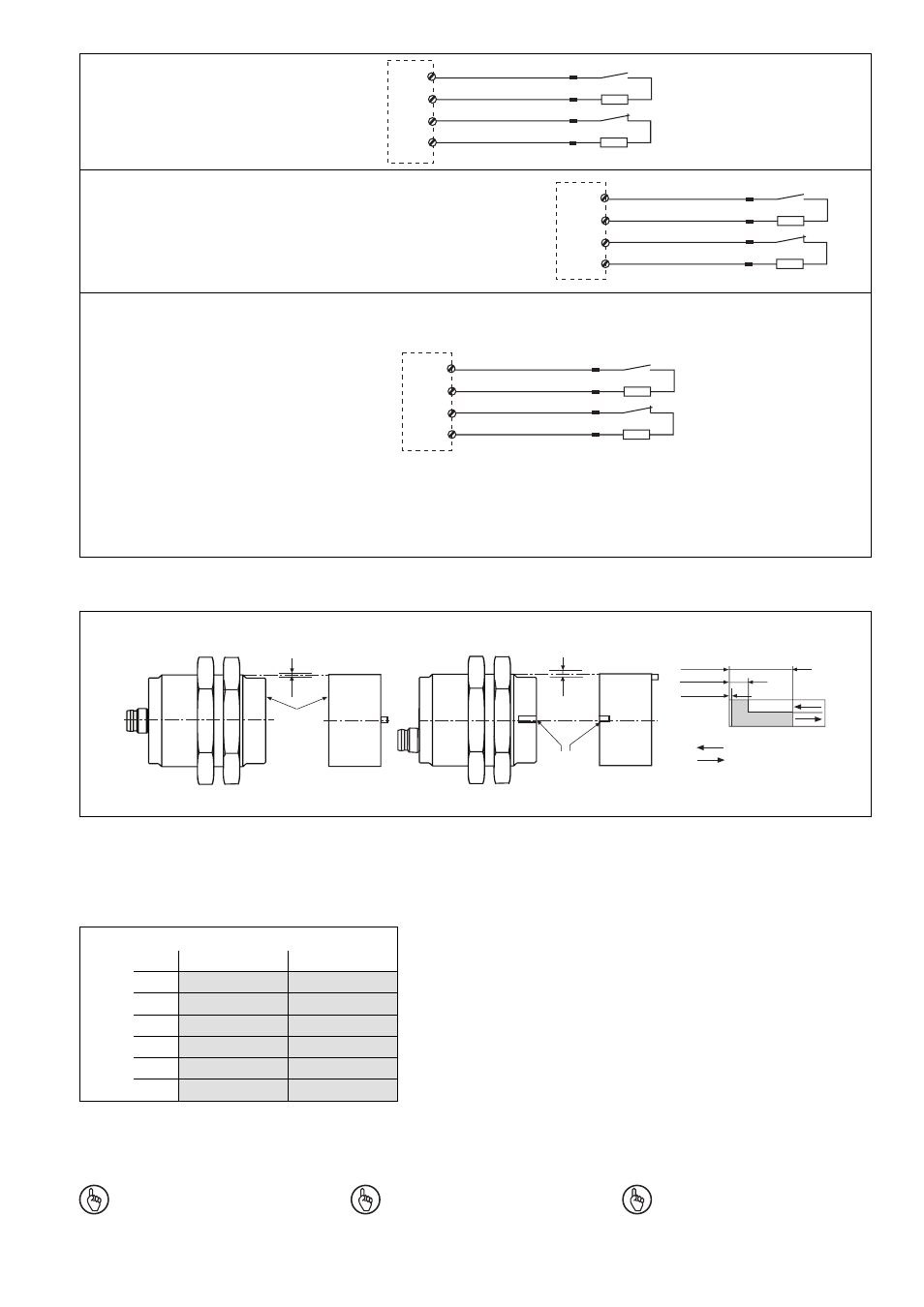
• Beispiel für PNOZmulti
• Example of PNOZmulti
• Exemple pour PNOZmulti
I0, I1:
Eingänge/Inputs/Entrées
T0, T1: Taktausgänge/Test pulse
outputs/Sorties impulsionnelle
• Beispiel für
Sicherheits-
steuerung PSS
• Example of PSS
safety system
• Exemple pour
automate PSS
1
2
3
4
O 16
O 17
blau/blue/bleu
weiß/white/blanc
braun/brown/marron
schwarz/black/noir
Taktausgang/Test pulse output/Sortie impulsionnelle
Eingang/Input/Entrée
I 00
I 01
Eingang/Input/Entrée
Taktausgang/Test pulse output/Sortie impulsionnelle
Beachten Sie:
• Schließerkontakt des PSEN an I0 anschlie-
ßen
• Öffnerkontakt des PSEN an I1 anschließen
Please note:
• Connect N/O contact from PSEN to I0
• Connect N/C contact from PSEN to I1
Important :
• raccordement du contact à fermeture du
PSEN à I0
• raccordement du contact à ouverture du
PSEN à I1
Schutztür, Schaltertyp 2/Safety gate, switch type 2/
Protecteur mobile, type du capteure 2
1
2
3
4
T0
T1
blau/blue/bleu
weiß/white/blanc
braun/brown/marron
schwarz/black/noir
I0
I1
Wichtig: Die Angaben in der Tabelle
"Max. Seiten- und Höhenversatz"
gelten bei oben liegenden Kerben
beim Sicherheitsschalter und beim
Betätiger.
Notice: The entries in the table "Max.
lateral and height offset" are valid for
top-aligned indentations of the safety
sensor and actuator.
Important : les valeurs du tableau
"Décalage latéral et décalage en
hauteur max" ne sont valables que
pour un montage avec les encoches
vers le haut du capteur et de l'aimant.
Kerbe
Indentation
Enchose
Seitenversatz/Lateral offset/
Décalage latéral
Höhenversatz/Height offset/
Décalage en hauteur
aktive Fläche active area surface
active
s
ao = 8
s
ar = 26
Ein/On/Marche
Aus/Off/Arrêt
s
omin = 0,5
Seiten- und Höhenversatz/Lateral and height offset/Décalage latéral et Décalage en hauteur
(Die angegebenen Werte sind gültig bei einer Temperatur von 20°C/The stated values are valid at a temperature of 20°C/Les valeurs indiquées
sont valables pour une température de 20°C.)
Gesicherter Schaltabstand S
ao
in mm/Assured operating distance S
ao
in mm/Portée de travail assurée S
ao
en mm
0,5
7,5
7,0
6,5
6,0
5,0
4,5
1,0
7,5
7,0
6,5
6,0
5,0
4,5
1,0
2,0
3,0
4,0
5,0
6,0
Gesicherter Ausschaltabstand S
ar
:
max. 26 mm bei allen Höhen- und Seiten-
versätzen
Assured release distance S
ar
:
max. 26 mm with all lateral and height
offsets
Portée de déclenchement assurée S
ar
:
max. 26 mm pour tous les décalages latéral
et les décalages en hauteur
Seitenversatz/Lateral offset/
Décalage latéral
Höhenversatz/Height offset/Décalage en hauteur
• PNOZ e5.13p
1
2
3
4
blau/blue/bleu
weiß/white/blanc
braun/brown/marron
schwarz/black/noir
A1
S32
A1
S44
- PSEN 2.2p-20 /8mm 1 switch PSEN 2.2-20 / 1 actuator PSEN 2.1-10 / 1 actuator PSEN 2.2p-21/PSEN2.2-20/LED/8mm 1unit PSEN 2.2p-20/PSEN2.2-20/8mm 1unit PSEN 1.2-20 / 1 actuator PSEN 1.1-20 / 1 actuator PSEN 1.1-10 / 1 actuator PNOZ m EF 2MM S1IM 230-240VAC IM 0.01-15 A S1IM 110-127VAC IM 0.01-15 A S1IM 24VDC IM 0.01-15 A UP S1IM 42-48VAC IM 0.01-15 A S1IM 24VAC IM 0.01-15 A S1IM 24VDC IM 0.01-15 A PNOZ 1 24VDC 3n/o 1n/c PNOZ 1 230-240VAC 3n/o 1n/c PNOZ 1 110-120VAC 3n/o 1n/c PNOZ 1 48VAC 3n/o 1n/c PNOZ 1 24VAC 3n/o 1n/c PSEN 2.1p-21/8mm/LED/1switch PSEN 2.1p-20/8mm/1switch PSEN 2.1p-21/PSEN 2.1-20 /8mm/LED/1unit PSEN 2.1p-20/PSEN 2.1-20 /8mm/1unit PSEN 2.1b-20/8mm/10m/ 1switch PSEN 2.1a-20/8mm/5m /1switch PSEN 2.1b-20/PSEN 2.1-20 /8mm/10m/1unit PSEN 2.1a-20/PSEN 2.1-20/8mm /5m/1unit PNOZ 2VJ 24VDC 3n/o 1n/c 2n/o t