Justage, Adjustment, Ajustement – Pilz PSEN 2.2p-21/LED/8mm 1 switch User Manual
Page 2: Raccordement, Anschlüsse, Connections
- 2 -
• Zwei Muttern M30 zur Befestigung des
Sicherheitsschalter sind im Lieferumfang
enthalten.
• Das Anzugsdrehmoment der Mutter M30
beträgt maximal 300 Ncm.
• Befestigen Sie den Betätiger mit einer
Schraube M4 oder M5. Verwenden Sie
eine Schraube aus nicht-magnetischem
Material (z. B. Messing).
Sicherheitsschalter und Betätiger
• von Eisenspänen fernhalten
• keinen starken Magnetfeldern aussetzen
• keinen starken Stößen oder Schwingun-
gen aussetzen
• nicht als Anschlag benutzen
Justage
• Der Sicherheitsschalter darf nur mit dem
zugehörigen Betätiger PSEN 2.2-20
verwendet werden.
• Prüfen Sie die Funktion immer mit einem
der zugelassenen Auswertegeräte.
• Beim PSEN 2.2p-21 leuchtet die LED bei
unbetätigten Reedkontakten (Schutzein-
richtung geöffnet oder Sicherheitsschalter
und Betätiger falsch justiert). Die LED
befindet sich im Öffnerkreis des
Sicherheitsschalter. Bei betätigten
Reedkontakten erlischt die LED.
• Die angegebenen Schaltabstände (siehe
technische Daten) gelten nur, wenn die
beiden Kerben am Sicherheitsschalter und
Betätiger gegenüberliegend ausgerichtet
montiert sind. Andere Anordnungen
können zu abweichenden Schaltab-
ständen führen.
• Beachten Sie den maximal zulässigen
Seiten- und Höhenversatz (siehe "Schalt-
abstände" und "Max. Seiten- und Höhen-
versatz"). Die Werte gelten nur bei nach
oben ausgerichteten Kerben von
Sicherheitsschalter und Betätiger.
• Two nuts M30 for fixing the safety sensor
are included in the package.
• The torque setting of the nut M30 may be
a maximum of 300 Ncm.
• Fix the actuator with an M4 or M5 screw.
Use a screw that is made from non-
magnetic material (e.g. brass).
Safety switch and actuator:
• keep away from iron cuttings
• do not expose to strong magnetic fields
• do not expose to strong shocks or vibration
• do not use as dead stop
Adjustment
• The safety switch must only be used in
conjunction with its respective actuator
PSEN 2.2-20.
• Always check the functions with one of the
approved evaluation devices.
• On PSEN 2.2p-21 the LED lights when
the reed contacts are not operated (safety
device is open or safety switch and
actuator are adjusted incorrectly). The
LED is in the N/C contact circuit of the
safety sensor. When the reed contacts
are operated, the LED will go out.
• The stated switch offsets (see technical
data) are only valid, when the two
indentations at the safety sensor and
actuator are mounted so that they are
aligned opposite each other. Different
layouts may lead to deviating switching
gaps.
• Please note the maximum permissible
lateral and height offset (see "Switching
distances" and "Max. lateral and height
offset"). These values are only valid for
top-aligned indentations of the safety
sensor and actuator.
• Deux écrous M30 sont livrés avec le
capteur pour sa fixation.
• Le couple de serrage des écrous M30 est
au max. de 300 Ncm.
• Fixer l'aimant à l'aide d'une vis M4 ou M5.
Utiliser une vis en métal non magnétiques
(par ex. laiton).
Le capteur de sécurité et l'actionneur :
• doivent être éloignés des copeaux
métalliques
• ne doivent pas être exposés à des champs
magnétiques élevés
• ne doivent pas subir des chocs et
vibrations importants
• ne doivent pas être utilisés comme butée
Ajustement
• Le capteur de sécurité ne peut être utilisé
qu'avec l'actionneur (aimant) PSEN 2.2-20.
• Testez la fonction uniquement avec une
des unités de contrôle autorisées.
• Sur le PSEN 2.2p-21, la LED est allumée
quand les contacts reed ne sont pas
actionnés (protecteur ouvert ou mauvais
alignement du capteur et de l'actionneur).
La LED est insérée dans le contact à
ouverture du capteur de sécurité. Quand
les contacts Reed sont actionnés, la LED
s'éteint.
• Les distances de commutation indiquées
(voir caractéristiques techniques) ne sont
valables que si, lors du montage, les
encoches du capteur et de l'aimant sont
face à face. Un autre montage peut
entraîner la modfication des distances de
commutation.
• Veuillez noter les valeurs des décalages
latéraux et en hauteur toléréés (voir
"Distances de commutation" et "décalage
latéral max. et décalage en hauteur
max."). Les valeurs ne sont valables que
pour un montage avec les encoches vers
le haut du capteur et de l'aimant.
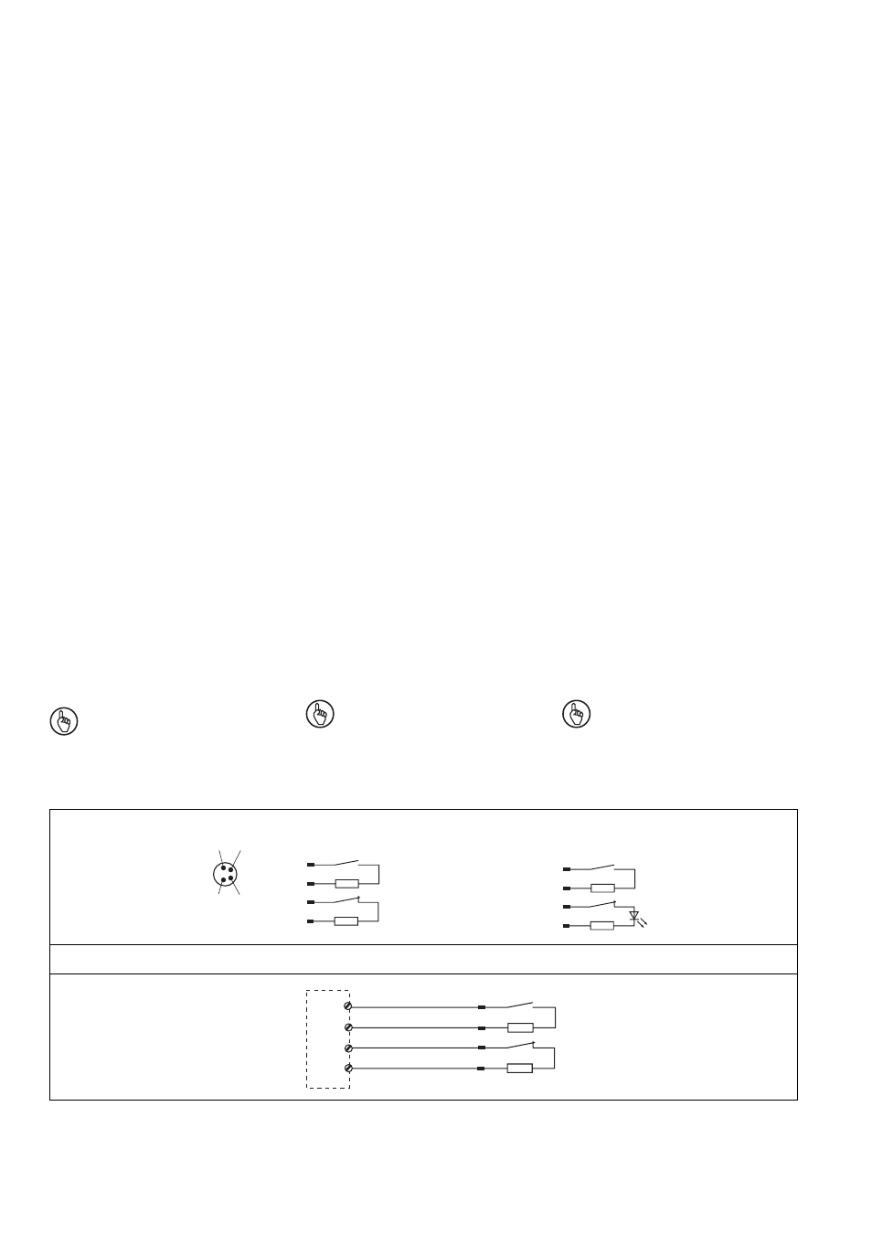
Raccordement
Notice: The colour marking of the
connection cables only applies to
cables available from Pilz as an
accessory.
The safety switch is shown in not operated
mode.
Important : Les repérages des
couleurs ne sont valables que pour les
câbles fournis par Pilz.
Le capteur de sécurité est représenté en
position non actionnée.
1
2
3
4
1
2
3
4
1
2
3 +
4
Belegung des
4pol. M8-Stiftsteckers/
Configuration of the 4-
pin M8 connector/
Repérage du
connecteur M8 4 br.
PSEN 2.2p-20
ohne/without/sans LED
PSEN 2.2p-21
mit/with/avec LED
Anschluss an Auswertegerät
• PNOZ e3.1p
• PNOZ e3vp 10s
• PNOZ e3vp 300s
1
2
3
4
blau/blue/bleu
weiß/white/blanc
braun/brown/marron
schwarz/black/noir
S11
S12
S23
S24
Connection to evaluation device
Raccordement à l'unité de contrôle
Anschlüsse
Wichtig: Die Farbkennzeichnung für
die Anschlussleitung gilt nur für die als
Zubehör erhältlichen Kabel von Pilz
Der Sicherheitsschalter ist in unbetätigtem
Zustand dargestellt
Connections
- PSEN 2.2p-20 /8mm 1 switch PSEN 2.2-20 / 1 actuator PSEN 2.1-10 / 1 actuator PSEN 2.2p-21/PSEN2.2-20/LED/8mm 1unit PSEN 2.2p-20/PSEN2.2-20/8mm 1unit PSEN 1.2-20 / 1 actuator PSEN 1.1-20 / 1 actuator PSEN 1.1-10 / 1 actuator PNOZ m EF 2MM S1IM 230-240VAC IM 0.01-15 A S1IM 110-127VAC IM 0.01-15 A S1IM 24VDC IM 0.01-15 A UP S1IM 42-48VAC IM 0.01-15 A S1IM 24VAC IM 0.01-15 A S1IM 24VDC IM 0.01-15 A PNOZ 1 24VDC 3n/o 1n/c PNOZ 1 230-240VAC 3n/o 1n/c PNOZ 1 110-120VAC 3n/o 1n/c PNOZ 1 48VAC 3n/o 1n/c PNOZ 1 24VAC 3n/o 1n/c PSEN 2.1p-21/8mm/LED/1switch PSEN 2.1p-20/8mm/1switch PSEN 2.1p-21/PSEN 2.1-20 /8mm/LED/1unit PSEN 2.1p-20/PSEN 2.1-20 /8mm/1unit PSEN 2.1b-20/8mm/10m/ 1switch PSEN 2.1a-20/8mm/5m /1switch PSEN 2.1b-20/PSEN 2.1-20 /8mm/10m/1unit PSEN 2.1a-20/PSEN 2.1-20/8mm /5m/1unit PNOZ 2VJ 24VDC 3n/o 1n/c 2n/o t