Fig. i, Fig. h, Fig. g – Thetford 19621 - Seal Replacement Package User Manual
Page 3: High profile only, Replacing flush nozzle seals
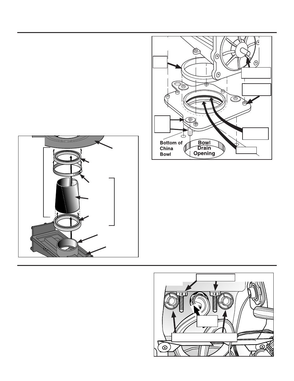
Replacing Flush Nozzle Seals
This does not require removing the Mechanism.
To Remove Old Parts
1. Disconnect 2 upper Tubes from outside Nozzle Connectors (Fig.
I).
2. Cut Tie Strap securing Solenoid Valve to Metal Bracket (Fig. J).
3. Being careful not to bend Metal Bracket, slide Solenoid Valve out
of slot in Bracket. Swing entire Valve/Hose Assembly down and to
right out of the way. Support it to avoid putting stress on the Wire
Harness.
4. Pop up Seat/Lid Bolt Covers (hinged from rear).
Fig. I
Hinge Post Bolts
Outside Nozzle Connectors
Locking
Nut
Part #19621
Seal Replacement Package
Page 3
Mounting
Flange
Fig. H
Shown
separate for
clarity – these
items nor-
mally remain
assembled
HIGH
PROFILE
ONLY
Extension
Tube
Mounting
Flange Seal
Extension
Tube Seal
Clamp
Flat Foam
Seal
Mechanism
Lead Screw
Blade
Seal
Mechanism
Plate
Sealant
Well-nut
ass’y
Fig. G
Mechanism
Tube Lip
Mechanism
some low-profile units, it may be a tight squeeze. Align mechanism over Mecha-
nism Plate, press down and secure with four screws (MS, Fig. D).
6. Turn toilet over to check centering. Loosen well-nuts to re-center if needed.
Do the permanent tightening down of the well-nut screws at this
time by hand. Tighten in a diagonal pattern to get an even seal. Be
careful not to overtighten and cause deflection of the plate at the
edges. Wipe off excess sealant when done.
7. Cut approximately 1” off Overflow Tube. Forming a full loop, reattach to
Mechanism. Tuck in and away from lead screw.
8. If you removed the Controller Assembly and/or the Switch Box, re-install
now, using the adhesive foam pads provided. If you removed Metal
Bracket, reinstall.
9.
High Profile: To install Extension Tube (Refer to Fig. H):
a. Lubricate sealing surface of Extension Tube Seal with silicone
grease.
b. Install Extension Tube Seal on Extension Tube.
c. Install Extension Tube and seal assembly on Mechanism. Make sure
that seal is seated at least 1/2 inch below Mechanism tube lip.
d. Ensure Hose Clamp on Mounting Flange Seal is tight.
e. Lubricate Mounting Flange Seal sealing surface with Silicone
Grease.
f. Install Mounting Flange and Seal assembly on Extension Tube. Make
sure there is at least a 1/2” overlap between the Extension Tube
and Mounting Flange Seal.
Low Profile: Replace the Mounting Flange Seal onto the lip of the
Mounting Flange. Install Mounting Flange to Mechanism. (No extension
tube is used.)
10. Replace 2 Mounting Bushings with flat surface out.