Fig. e, Fig. d, Fig. f – Thetford 19621 - Seal Replacement Package User Manual
Page 2
Part #19621
Seal Replacement Package
Page 2
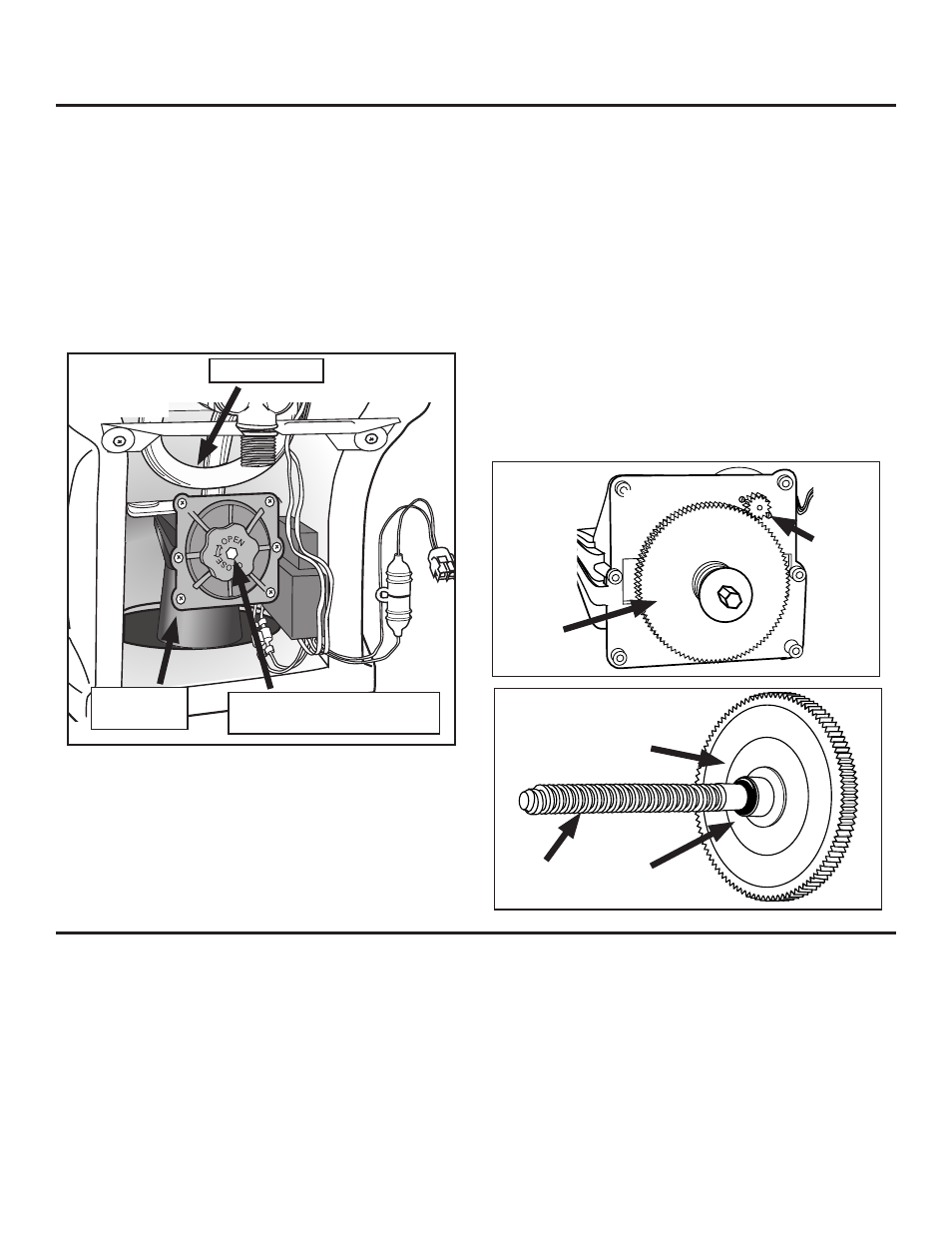
Fig. E
Pinion
Gear
Gear/clutch as-
sembly
To Replace O-Ring Seal
If you do not need to replace this seal, skip down to
Re-install Mechanism sec-
tion below.
It is not necessary to remove Mechanism from toilet to install this seal. If you decide
to remove it, disconnect the Overflow tube from top of Mechanism by twisting it off.
Then disconnect the yellow and green Motor Lead, using pliers if necessary.
1. Remove the Sound Deadening Kit insulation (if present) from Mechanism by
unwrapping the Velcro
TM
strap.
2. Remove 6 End Cap Bolts from Mechanism. Remove End Cap (Fig. D).
3. Grasp Gear/Clutch Assembly (Fig. E) and pull it out of the housing. This retracts
Fig. D
Mechanism
End Cap
Mechanism Lead Screw (knob
shown not on all units)
Overflow Tube
Fig. F
“O” Ring
Seal
Lead
Screw
To Replace Hopper (Bowl Opening) Seal
If
you do not need to replace this seal, skip down to
Re-install Mechanism
section below.
1. Unscrew 3 Well Nut Screws with Washers (shown without arrows in Fig. C, page
1) to free white Mechanism Plate.
2. Scrape off old Seal on china with sharp tool. Use mineral spirits to remove
residue.
3. Apply a generous ring of caulk sealant around Bowl Drain opening (Fig. G, next
page).
4. Apply Flat Foam Seal to caulk sealant. Press down in place, center the seal, and
wipe away any excess sealant squeezed into opening.
To Replace Mechanism
1. Wet blade seal with clean water.
2. Fully seat new blade seal, lip up, onto Mechanism Plate (Fig. G).
3. To avoid damaging blade seal, make sure blade in new mechanism is fully closed.
Turn mechanism lead screw counter-clockwise to close valve (Fig. D).
4. Connect 2 Motor Leads, yellow-yellow, green-green (Fig. A).
5. Working from the back, position Mechanism in Toilet. NOTE: on
the Valve Blade fully. The Lead Screw (Fig. F) is engaged in the Lead Screw
Boss on the Valve Blade (not shown).
4. Turn Lead Screw counterclockwise until it releases from the Valve Blade.
Withdraw the entire Gear/Clutch/Lead Screw Assembly.
5. On the back side of the Gear/Clutch subassembly (Fig. F) you will find a small
black “O” Ring. Slide it off and replace it with the new one.
6. Slide the Gear/Clutch/Lead Screw Assembly back into the housing. Holding
the Valve Blade, turn Lead Screw clockwise enough turns to fully engage the
Lead Screw into the Valve Blade. Release the Valve Blade.
(Caution: wear
gloves when handling Valve Blade or anything that may have
come in contact with waste.)
7. Re-engage the large gear with the small pinion gear (Fig .E) and slide the Gear/
Clutch/Lead Screw Assembly fully into the housing.
8. Make sure curved washer is in place on the Lead Screw, concave side facing
toilet. Reinstall End Cap and secure 6 Screws.
9. Replace the Sound Deadening Kit insulation (if present) onto Mechanism, securing
it with the Velcro
TM
strap.
If you have removed Mechanism from toilet, do these steps now:
1. Reattach Overflow Tube to Mechanism.
2. Reattach 2 Wire Motor Leads, yellow to yellow and green to green.
Gear/clutch assembly