Vessel attachments, Piping, Example ii – Rice Lake Weigh Modules/Mount Assemblies User Manual
Page 56
VESSEL ATTACHMENTS
3-4
Piping
For example, if a vessel’s live load is 50,000 lb and a system accuracy
of .25% is required, then
F
≤
.1 x .25 x 50,000
F
≤
1,250 lb.
i.e., the sum of all vertical pipe forces must be less than or equal to
1,250 lb.
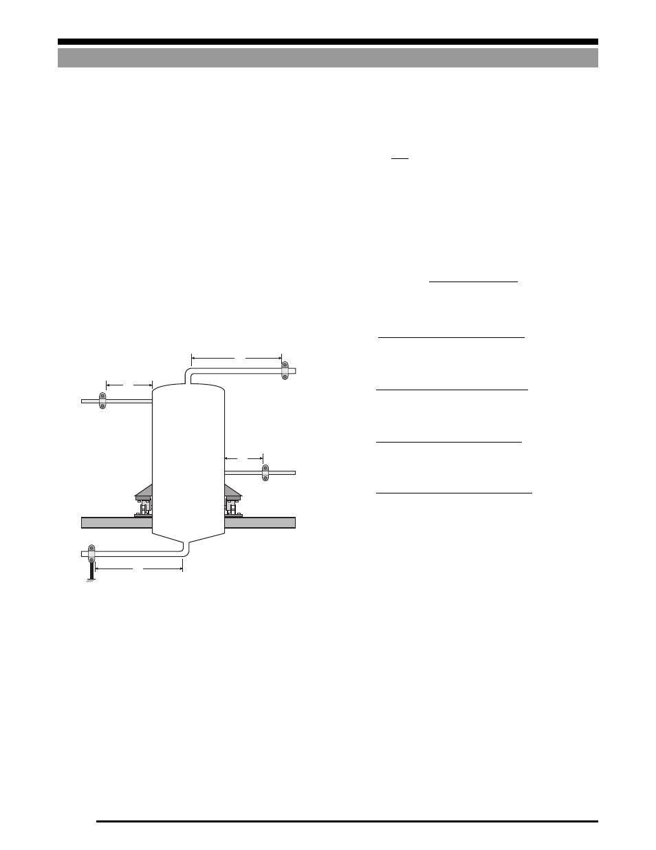
Example II:
The vessel shown in Figure 3-4 has the following characteristics:
•
40,000 lb live load
•
mounted on 4 each 20,000 lb single-ended beams with full
scale deflections of .010"
•
structure deflection of .375"
•
accuracy requirement of 0.5%
•
material is stainless steel throughout
2" Schedule 10S
Pipe 2
Pipe 1
Pipe 3
Pipe 4
3" Schedule 40
1" Schedule 40
3" Schedule 40
60"
84"
36"
72"
Figure 3-4
Step 1
Determine allowable F value from equation 2,
F
≤
.1 x system accuracy (%) x live load (lb)
F
≤
.1 x 0.5 x 40,000
≤
2,000 lb
The sum of all vertical pipe forces must be less than or equal to 2,000
lb.
Step 2
Determine total deflection. Since the live load represents only 1/2
of the load cell capacity, the load cell deflection will be
Total deflection
∆
h = load cell deflection + structure deflection
= .005 + .375
= .380"
Step 3
Determine F
x
for each pipe using the formula:
a)
= 1,029 lb.
b)
= 391 lb.
c)
= 648 lb.
d)
= 239 lb.
Step 4
Determine F using the formula: F = F
1
+ F
2
+ F
3
+ F
4
F = 1,029 + 391 + 648 + 239 = 2,307 lb
Since F calculated for the vessel is greater than the value deter-
mined in Step 1, this is not acceptable. There are several solutions.
1)
Accept a lower accuracy (perhaps 1%, instead of .5%).
2)
Reduce the deflection of the support structure.
3)
Improve the piping by:
a)
using smaller, lighter pipes
b)
use flexible hose or bellows
c)
increase the distance to the first pipe support points
If we apply 3 above to this vessel then we would focus our attention
on the main offender, pipe 1. The problem can be solved simply by
increasing the distance to the first support from 72" to 82", yielding
an F1 = 697 lb. Hence, F = 697 + 391 + 648 + 239 = 1,975 lb.
This is less than 2,000 lb, so the design is now acceptable.
36
3
F
4
=
.59(1.315
4
– 1.049
4
) x .380 x 28,000,000
60
3
F
2
=
.59(2.375
4
– 2.07
4
) x .380 x 28,000,000
84
3
F
3
=
.59(3.50
4
– 3.07
4
) x .380 x 28,000,000
72
3
F
1
=
.59(3.50
4
– 3.07
4
) x .380 x 28,000,000
l
3
F
x
=
.59(D
4
– d
4
) x (Dh) x E
2
= .005"
.010