Stay rod expansion/contraction, Vessel expansion/contraction, System design – Rice Lake Weigh Modules/Mount Assemblies User Manual
Page 14: Thermal expansion, 48" 1" dia
SYSTEM DESIGN
1-12
Thermal Expansion
Calculating Thermal Expansion of Vessels & Stay Rods
Stay Rod Expansion/Contraction
Stay rods attached to vessels subjected to thermal changes can
introduce significant forces which affect system accuracy. The
method of attachment and the length of the stay rods directly affect
these forces.
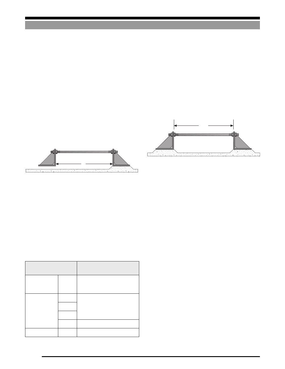
Figure 1-19 illustrates a stay rod rigidly attached to a bracket on
each end—one bracket is rigidly mounted, the other is unattached,
thus allowing the rod to expand and contract freely. As the tem-
perature rises or drops, the length of the rod will increase or
decrease respectively. The change in length (
∆
L) is proportional to
the original length (L), the change in temperature (
∆
T), and the
coefficient of linear expansion (a) which is a characteristic of the
rod material.
∆
L can be calculated from the following equation:
∆
L = a x
L x
∆
T
Figure 1-19
Table 1-1 below lists the coefficient of thermal expansion (
α
) for
various materials used to construct vessels and stay rods.
Example:
If the rod in Figure 1-19 is made from 1018 steel, then a = 6.5 x 10
-
6
from Table 1-1. If the rod is 48" long and the temperature
increases by 60
°
F, the length of the rod will increase by:
∆
L = a x L x
∆
T
∆
L = 6.5 x 10
-6
x 48" x 60
∆
L = .019
This shows that a 48" steel rod will increase by .019" as a result of
a 60
°
F temperature rise. This may seem insignificant, until you
consider the forces which can result if the stay rod is confined
rigidly at each end, as in Figure 1-20.
In Figure 1-20, a 1" steel rod 48" long is attached to a bracket on
each end, and both brackets are rigidly attached. If the rod is
initially adjusted so that there is no strain, a subsequent 60
°
F rise
in temperature will cause the rod to exert a force of 9,000 lb on each
bracket. Hence, vessel restraint systems must be designed and
installed properly so that they don’t move and/or apply large lateral
forces to the weigh vessel.
Vessel Expansion/Contraction
Temperature fluctuations will cause weigh vessels to grow and
contract. Figure 1-21 on the following page best illustrates this.
Shown is a top view of a rectangular vessel. The solid line repre-
sents its size at 70
°
F and the inner and outer broken lines represent
its size at 40
°
F and 100
°
F respectively. The amount that the sides
will increase/decrease in length can be found using the expansion
formula discussed previously.
Therefore:
∆
L = X x L x
∆
T
L
Figure 1-20
48"
1" Dia
l
a
i
r
e
t
a
M
n
o
i
s
n
a
p
x
E
r
a
e
n
i
L
f
o
t
n
e
i
c
if
f
e
o
C
r
e
p
s
e
h
c
n
i(
°
)
F
l
e
e
t
S
w
o
L
n
o
b
r
a
c
)
8
1
0
1
(
0
1
x
5
.
6
6
-
l
e
e
t
s
s
s
e
l
n
i
a
t
S
2
0
3
0
1
x
6
.
9
6
-
3
0
3
4
0
3
6
1
3
0
1
x
9
.
8
6
-
m
u
n
i
m
u
l
A
1
6
0
6
0
1
x
0
.
3
1
6
-
Table 1-1