2 serial communications, 4 cpu board replacement, Table 2-2. j2 pin assignments – Rice Lake Survivor 390HE Hostile Environment Digital Indicator User Manual
Page 9: Installation 5
Installation
5
2.3.2
Serial Communications
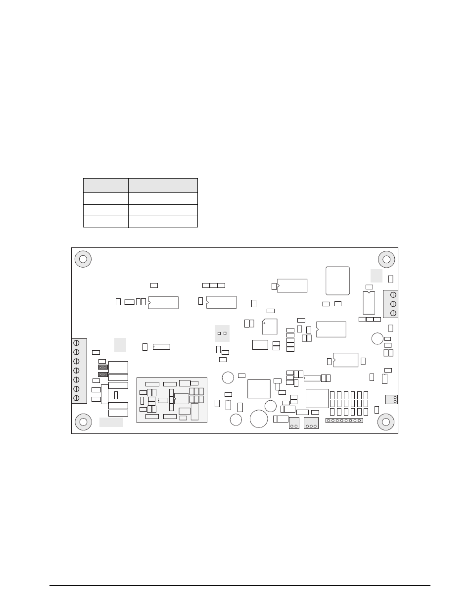
To attach serial communications cables, remove
connector J2 from the board (see Figure 2-2). Connect
communications cable through cord grip to connector
J2 as shown in Table 2-2.
Once cables are attached, reconnect J2 to the header
on the board.
The 390HE serial port supports full duplex RS-232
communications for connections to printers, PCs, and
other attached devices. See Section 3.0 on page 8 for
general configuration information; see Section 3.2.4
on page 16 for serial port configuration.
2.4
CPU Board Replacement
If you must remove the 390HE CPU board, use the
following procedure:
1. Disconnect power to the indicator. Loosen
cord grips and open enclosure.
2. Unplug all connections to the CPU board. See
Figure 2-2 on page 5 for connector locations.
3. Remove the four nuts from the corners of the
CPU board.
4. Remove the CPU board from the enclosure.
To replace the CPU board, reverse the above
procedure. Be sure to reinstall cable ties to secure all
cables inside the indicator enclosure.
Figure 2-2. 390HE CPU Board
J2 Pin
Function
1
RS-232 TxD
2
RS-232 Ground
3
RS-232 RxD
Table 2-2. J2 Pin Assignments
1
J3
VR2
XT2
VR3
U12
XT1
U2
JP3
U5
U10
JP1
U1
JP2
C27
C26
C28
C29
C30
C31
J1
U14
R1
C4
C3
C7
R6
U7
C19
C18
R7
C16
R8
R9
C20
C21
D2
R29
R26
R25
C45
C46
C47
R23
C48
C49
U13
C42
DR1
R16
L1
L2
1
1
J4
J5
U8
U3
FLASH RAM
J2
U6
U11
C25
VR1
C15
C22
R10
C9
C10
C11
C14
U9
R11
R13
R12
C24
C58
C65
C64
R44
R45
C63
R42
R43
R41
R40
C62
C61
R38
R39
R28
C56
C60
R36
R37
R35
R34
C59
R30
R31
EMI1
F1
J6
C13
C12
C8
R4
C23
C57
C5A
C44
C41
C43
C53
C52
C17
R24
C51
C6
C5
R3
U4
C2
D3
R2
–EXC
+EXC
SHIELD
–SENSE
+SENSE
–SIG
+SIG
7
6
5
4
3
2
1
LOAD CELL
CONNECTOR
RxD
GND
TxD
3
2
1
R14
R15
DR2
C34
C35
C36
C37
R19
R20
C33
C38
C39
C40
C32
R17
R18
R21
R22
Keypad Connector
SERIAL PORT
Power Supply
Input
To Setup
Switch
Microcontroller
+
R5
R10A
R10B
Q1
C50
+
C54
+
C54A
+
D1
C58A
R26B
Q2
R26A
C55
C55A
R27
VR4
C1
C66